Add initial support for Freescale Kinetis TWR-K70F120M development kit
Subsystems (11)
v2 cover Add initial support for Freescale Kinetis TWR-K70F120M development kit
This is the second iteration of the patchset that adds a basic initial support to TWR-K70F120M development kit which is based on ARM Cortex-M4 Freescale Kinetis K70 SoC.
Previous iteration met with a broad response for which I would like to thank everyone involved.
Following is the change list:
1. First three ('controversial') patches are removed.
As long as it doesn't hit platform stability, I don't use these Cortex-M compiler flags, it should not stop the whole of the patchset.
The idle quirks issue is now addressed by adding idle.c which provides callback for arm_pm_idle.
The infamous zlib patch was not needed at all - I didn't really check what it was protecting against.
2. include/mach/idle.h file removed.
3. kinetis_platform.c renamed to kinetis.c, obj-$(CONFIG_MACH_KINETIS) changed to obj-y, CONFIG_MACH_KINETIS not needed anymore, removed with the whole of the Kconfig file in mach-kinetis directory.
4. Assuming that fsl-edma and fsl-lpuart drivers handle big-endian properly, pinctrl, clk and timer drivers now support big-endian the same way ("big-endian" option in .dts).
5. All addresses based on KINETIS_AIPS0PERIPH_BASE and KINETIS_AIPS1PERIPH_BASE are moved to DT. The struct kinetis_sim_regs is moved to clk-kinetis.c. As a result whole include/mach/kinetis.h is now removed.
6. Removed kinetis_map_io() from kinetis.c (formerly kinetis_platform.c).
7. Removed kinetis_init() function along with a call to of_platform_populate().
8. Removed MACH_KINETIS from arch/arm/tools/mach-types, removed inclusion of asm/mach-types.h in kinetis.c (formerly kinetis_platform.c).
9. Removed inclusion of linux/clk.h from clk-kinetis.c.
10. Clock and timer drivers are in separate patches now.
11. '&& ARM' removed from drivers/clocksource/Kconfig.
12. s/clk/evt/ in timer-kinetis.c (actually, the affected *_set_mode() function is replaced by a set of *_set_state_*() functions).
13. Removed pointless raw_local_irq_save/restore() from timer-kinetis.c.
14. Removed overhead () from each of the &(.....) from timer-kinetis.c.
15. Removed unused KINETIS_PITn_IRQ definitions from timer-kinetis.c.
16. Replaced use of IRQ actions with request_irq() in timer-kinetis.c.
17. Removed all uses of KINETIS_MKCG() macro and whole include/mach/power.h
- now all clock gate details are specified directly in the DT. For each clock gate #clock-cells = <2> where the first part of the gate address is zero-based gate register number, the second part is the bit index.
18. Shortened long timer names in timer-kinetis.c.
19. Ensured module friendliness of pinctrl driver (tristate CONFIG_PINCTRL_KINETIS)
20. Removed txirq_names[] array from fsl-edma.c - sprinft()-generated strings used instead.
21. fsl-lpuart and fsl-edma related patches are both split into two:
1) changes in the driver and 2) use in platform.
22. Removed all occurences of CONFIG_ARCH_KINETIS from fsl-edma.c - now it looks more like fsl-lpuart driver (boolean 'kinetis' field in the main driver structure).
Paul Osmialowski (9):
arm: allow copying of vector table to internal SRAM memory
arm: twr-k70f120m: basic support for Kinetis TWR-K70F120M
arm: twr-k70f120m: clock driver for Kinetis SoC
arm: twr-k70f120m: timer driver for Kinetis SoC
arm: twr-k70f120m: IOMUX driver for Kinetis SoC
arm: twr-k70f120m: extend Freescale eDMA driver with the ability to
support Kinetis SoC
arm: twr-k70f120m: use Freescale eDMA driver with Kinetis SoC
arm: twr-k70f120m: extend Freescale lpuart driver with ability to
support Kinetis SoC
arm: twr-k70f120m: use Freescale lpuart driver with Kinetis SoC
 Documentation/devicetree/bindings/arm/fsl.txt      |   6 +
 .../devicetree/bindings/clock/kinetis-clock.txt    |  63 +++
 Documentation/devicetree/bindings/dma/fsl-edma.txt |  38 +-
 .../bindings/pinctrl/fsl,kinetis-pinctrl.txt       |  31 ++
 .../devicetree/bindings/serial/fsl-lpuart.txt      |   6 +-
 .../bindings/timer/fsl,kinetis-pit-timer.txt       |  50 ++
 arch/arm/Kconfig                                   |  16 +-
 arch/arm/Kconfig-nommu                             |  12 +
 arch/arm/Makefile                                  |   1 +
 arch/arm/boot/dts/kinetis-twr-k70f120m.dts         |  43 ++
 arch/arm/boot/dts/kinetis.dtsi                     | 241 +++++++++
 arch/arm/kernel/entry-v7m.S                        |   3 +
 arch/arm/mach-kinetis/Makefile                     |   5 +
 arch/arm/mach-kinetis/Makefile.boot                |   3 +
 arch/arm/mach-kinetis/idle.c                       |  27 +
 arch/arm/mach-kinetis/include/mach/memory.h        |  61 +++
 arch/arm/mach-kinetis/kinetis.c                    |  34 ++
 arch/arm/mm/Kconfig                                |   1 +
 arch/arm/mm/proc-v7m.S                             |  11 +
 drivers/clk/Makefile                               |   1 +
 drivers/clk/clk-kinetis.c                          | 463 ++++++++++++++++++
 drivers/clocksource/Kconfig                        |   5 +
 drivers/clocksource/Makefile                       |   1 +
 drivers/clocksource/timer-kinetis.c                | 321 ++++++++++++
 drivers/dma/fsl-edma.c                             | 114 ++++-
 drivers/pinctrl/freescale/Kconfig                  |   8 +
 drivers/pinctrl/freescale/Makefile                 |   1 +
 drivers/pinctrl/freescale/pinctrl-kinetis.c        | 541 +++++++++++++++++++++
 drivers/tty/serial/fsl_lpuart.c                    |  90 +++-
 29 files changed, 2153 insertions(+), 44 deletions(-)
 create mode 100644 Documentation/devicetree/bindings/clock/kinetis-clock.txt
 create mode 100644 Documentation/devicetree/bindings/pinctrl/fsl,kinetis-pinctrl.txt
 create mode 100644 Documentation/devicetree/bindings/timer/fsl,kinetis-pit-timer.txt
 create mode 100644 arch/arm/boot/dts/kinetis-twr-k70f120m.dts
 create mode 100644 arch/arm/boot/dts/kinetis.dtsi
 create mode 100644 arch/arm/mach-kinetis/Makefile
 create mode 100644 arch/arm/mach-kinetis/Makefile.boot
 create mode 100644 arch/arm/mach-kinetis/idle.c
 create mode 100644 arch/arm/mach-kinetis/include/mach/memory.h
 create mode 100644 arch/arm/mach-kinetis/kinetis.c
 create mode 100644 drivers/clk/clk-kinetis.c
 create mode 100644 drivers/clocksource/timer-kinetis.c
 create mode 100644 drivers/pinctrl/freescale/pinctrl-kinetis.c
Signature · 1 line
2.3.6
PATCH v2 1/9 arm: allow copying of vector table to internal SRAM memory
Based on part of the commit published on Emcraft git repo:
https://github.com/EmcraftSystems/linux-emcraft.git
2ce1841b590d014d8738215fb1ffe05f53c8d9f0 "some commit"
by: Dmitry Cherkassov <[email protected]>
The ARM v7M allows setting the vector table either in the boot memory or in the internal SRAM memory, controlled by Bit 29 in the Vector Table Base register. This implies that the OS vector table needs to be copied to the internal RAM.
New option CONFIG_COPY_VECTOR_TABLE_TO_SRAM_ADDR allows specification of the desired destination for the OS vector table.
---
 arch/arm/Kconfig-nommu      | 11 +++++++++++
 arch/arm/kernel/entry-v7m.S |  3 +++
 arch/arm/mm/proc-v7m.S      | 11 +++++++++++
 3 files changed, 25 insertions(+)
arch/arm/Kconfig-nommu +11 -0
@@ -62,3 +62,14 @@ config ARM_MPU If your CPU has an MPU then you should choose 'y' here unless you know that you do not want to use the MPU. + +config COPY_VECTOR_TABLE_TO_SRAM_ADDR + hex 'If non-zero, copy Vector Table to this SRAM Address' if CPU_V7M + default 0x00000000 + depends on CPU_V7M + help + The ARM v7M allows setting the vector table either in + the boot memory or in the internal SRAM memory, controlled + by Bit 29 in the Vector Table Base register. + This implies that the OS vector table needs to be copied to + the internal RAM.
arch/arm/kernel/entry-v7m.S +3 -0
@@ -146,3 +146,6 @@ ENTRY(vector_table) .rept CONFIG_CPU_V7M_NUM_IRQ .long __irq_entry @ External Interrupts .endr +#if CONFIG_COPY_VECTOR_TABLE_TO_SRAM_ADDR > 0x00000000 +ENTRY(vector_table_end) +#endif
arch/arm/mm/proc-v7m.S +11 -0
@@ -83,7 +83,18 @@ ENDPROC(cpu_v7m_do_resume) __v7m_setup: @ Configure the vector table base address ldr r0, =BASEADDR_V7M_SCB +#if CONFIG_COPY_VECTOR_TABLE_TO_SRAM_ADDR > 0x00000000 + ldr r12, =CONFIG_COPY_VECTOR_TABLE_TO_SRAM_ADDR + mov r5, r12 @ Copy the kernel vector_table to + ldr r6, =vector_table @ the in-SRAM vector table + ldr r4, =vector_table_end +1: ldr r3, [r6], #4 + str r3, [r5], #4 + cmp r6, r4 + bne 1b @ End of the copy code +#else ldr r12, =vector_table +#endif str r12, [r0, V7M_SCB_VTOR] @ enable UsageFault, BusFault and MemManage fault.
Signature · 1 line
2.3.6
PATCH v2 2/9 arm: twr-k70f120m: basic support for Kinetis TWR-K70F120M
In reply to Paul OsmialowskiThis one was inspired by a serie of commits published on Emcraft git repo:
https://github.com/EmcraftSystems/linux-emcraft.git
Entry commit: f014da1df860ad702d923c95cb97e068bd302cb0
RT75957. twr-k70f120m: basic support
by: Alexander Potashev <[email protected]>
---
 Documentation/devicetree/bindings/arm/fsl.txt |  6 +++++
 arch/arm/Kconfig                              |  9 ++++++-
 arch/arm/Kconfig-nommu                        |  1 +
 arch/arm/Makefile                             |  1 +
 arch/arm/boot/dts/kinetis-twr-k70f120m.dts    | 16 +++++++++++++
 arch/arm/boot/dts/kinetis.dtsi                |  5 ++++
 arch/arm/mach-kinetis/Makefile                |  5 ++++
 arch/arm/mach-kinetis/Makefile.boot           |  3 +++
 arch/arm/mach-kinetis/idle.c                  | 27 +++++++++++++++++++++
 arch/arm/mach-kinetis/kinetis.c               | 34 +++++++++++++++++++++++++++
 arch/arm/mm/Kconfig                           |  1 +
 11 files changed, 107 insertions(+), 1 deletion(-)
 create mode 100644 arch/arm/boot/dts/kinetis-twr-k70f120m.dts
 create mode 100644 arch/arm/boot/dts/kinetis.dtsi
 create mode 100644 arch/arm/mach-kinetis/Makefile
 create mode 100644 arch/arm/mach-kinetis/Makefile.boot
 create mode 100644 arch/arm/mach-kinetis/idle.c
 create mode 100644 arch/arm/mach-kinetis/kinetis.c
Documentation/devicetree/bindings/arm/fsl.txt +6 -0
@@ -135,3 +135,9 @@ LS2085A ARMv8 based Simulator model Required root node properties: - compatible = "fsl,ls2085a-simu", "fsl,ls2085a"; +Freescale Kinetis SoC Device Tree Bindings +------------------------------------------ + +TWR-K70F120M Kinetis K70 based development board. +Required root node compatible properties: + - compatible = "fsl,kinetis-twr-k70f120m"
arch/arm/Kconfig +8 -1
@@ -964,6 +964,13 @@ config ARCH_EFM32 Support for Energy Micro's (now Silicon Labs) efm32 Giant Gecko processors. +config ARCH_KINETIS + bool "Freescale Kinetis MCU" + depends on ARM_SINGLE_ARMV7M + select ARMV7M_SYSTICK + help + This enables support for the Freescale Kinetis MCUs + config ARCH_LPC18XX bool "NXP LPC18xx/LPC43xx" depends on ARM_SINGLE_ARMV7M
@@ -1733,7 +1740,7 @@ source "mm/Kconfig"
 config FORCE_MAX_ZONEORDER
 	int "Maximum zone order" if ARCH_SHMOBILE_LEGACY
 	range 11 64 if ARCH_SHMOBILE_LEGACY
-	default "12" if SOC_AM33XX
+	default "12" if SOC_AM33XX || ARCH_KINETIS
 	default "9" if SA1111 || ARCH_EFM32
 	default "11"
 	help
arch/arm/Kconfig-nommu +1 -0
@@ -65,6 +65,7 @@ config ARM_MPU config COPY_VECTOR_TABLE_TO_SRAM_ADDR hex 'If non-zero, copy Vector Table to this SRAM Address' if CPU_V7M + default 0x20000000 if ARCH_KINETIS default 0x00000000 depends on CPU_V7M help
arch/arm/Makefile +1 -0
@@ -170,6 +170,7 @@ machine-$(CONFIG_ARCH_IOP32X) += iop32x machine-$(CONFIG_ARCH_IOP33X) += iop33x machine-$(CONFIG_ARCH_IXP4XX) += ixp4xx machine-$(CONFIG_ARCH_KEYSTONE) += keystone +machine-$(CONFIG_ARCH_KINETIS) += kinetis machine-$(CONFIG_ARCH_KS8695) += ks8695 machine-$(CONFIG_ARCH_LPC18XX) += lpc18xx machine-$(CONFIG_ARCH_LPC32XX) += lpc32xx
arch/arm/boot/dts/kinetis-twr-k70f120m.dts new file +16 -0
@@ -0,0 +1,16 @@ +/* + * Device tree for TWR-K70F120M development board. + * + */ + +/dts-v1/; +#include "kinetis.dtsi" + +/ { + model = "Freescale TWR-K70F120M Development Kit"; + compatible = "fsl,kinetis-twr-k70f120m"; + + memory { + reg = <0x8000000 0x8000000>; + }; +};
arch/arm/boot/dts/kinetis.dtsi new file +5 -0
@@ -0,0 +1,5 @@ +/* + * Device tree for Freescale Kinetis SoC. + * + */ +#include "armv7-m.dtsi"
arch/arm/mach-kinetis/Makefile new file +5 -0
@@ -0,0 +1,5 @@ +# +# Makefile for the Freescale Kinetis platform files +# + +obj-y += kinetis.o idle.o
arch/arm/mach-kinetis/Makefile.boot new file +3 -0
@@ -0,0 +1,3 @@ + zreladdr-y := 0x08008000 +params_phys-y := 0x08000100 +initrd_phys-y := 0x08100000
arch/arm/mach-kinetis/idle.c new file +27 -0
@@ -0,0 +1,27 @@ +/* +* arch/arm/mach-kinetis/idle.c +*/ + +#include <linux/init.h> +#include <linux/io.h> +#include <asm/system_misc.h> +#include <asm/proc-fns.h> + +static void kinetis_idle (void ) +{ + asmvolatile ("wfi" ); + +/* +* This is a dirty hack that invalidates the I/D bus cache +* on Kinetis K70. This must be done after idle. +*/ +writel (readl (IOMEM (0xe0082000 )) |0x85000000 ,IOMEM (0xe0082000 )); +} + +static int __init kinetis_idle_init (void ) +{ + arm_pm_idle = kinetis_idle; +return 0 ; +} + +arch_initcall (kinetis_idle_init);
arch/arm/mach-kinetis/kinetis.c new file +34 -0
@@ -0,0 +1,34 @@ +/* +* kinetis.c - Freescale Kinetis K70F120M Development Board +* +* Based on legacy pre-OF code by Alexander Potashev <[email protected]> +* +* (C) Copyright 2011, 2012 +* Emcraft Systems, <www.emcraft.com> +* Alexander Potashev <[email protected]> +* +* Copyright (C) 2015 Paul Osmialowski <[email protected]> +* +* This program is free software; you can redistribute it and/or modify it under +* the terms of the GNU General Public License version 2 as published by the +* Free Software Foundation. +*/ + +#include <linux/kernel.h> +#include <linux/init.h> +#include <linux/of_platform.h> +#include <asm/v7m.h> +#include <asm/mach/arch.h> + +static const char *const kinetis_compat[]__initconst = { +"fsl,kinetis-twr-k70f120m" , +NULL +}; + +/* +* Freescale Kinetis platform machine description +*/ +DT_MACHINE_START (KINETIS ,"Freescale Kinetis" ) + .dt_compat = kinetis_compat, + .restart = armv7m_restart, +MACHINE_END
arch/arm/mm/Kconfig +1 -0
@@ -609,6 +609,7 @@ config CPU_V7M_NUM_IRQ depends on CPU_V7M default 90 if ARCH_STM32 default 38 if ARCH_EFM32 + default 106 if ARCH_KINETIS default 112 if SOC_VF610 default 240 help
Signature · 1 line
2.3.6
PATCH v2 3/9 arm: twr-k70f120m: clock driver for Kinetis SoC
In reply to Paul OsmialowskiBased on K70P256M150SF3RM.pdf K70 Sub-Family Reference Manual, Rev. 3.
---
 .../devicetree/bindings/clock/kinetis-clock.txt    |  63 +++
 arch/arm/boot/dts/kinetis.dtsi                     |  36 ++
 drivers/clk/Makefile                               |   1 +
 drivers/clk/clk-kinetis.c                          | 463 +++++++++++++++++++++
 4 files changed, 563 insertions(+)
 create mode 100644 Documentation/devicetree/bindings/clock/kinetis-clock.txt
 create mode 100644 drivers/clk/clk-kinetis.c
Documentation/devicetree/bindings/clock/kinetis-clock.txt new file +63 -0
@@ -0,0 +1,63 @@ +* Clock bindings for Freescale Kinetis SoC + +Required properties: +- compatible: Should be "fsl,kinetis-cmu". +- reg: Two address ranges, one for the Clock Genetator register set, + one for System Integration Module register set. +- Set of clock devices: one fixed-rate-root, fixed-rate clocks and clock-gates. + +For clock-gate addresses see K70 Sub-Family Reference Manual, Rev. 3 pg. 341 +and later. Notice that addresses are zero-based, so SIM_SCGC1 has address 0, +SIM_SCGC2 has address 1 and so on. The second address component is the bit +index. + +Example: + +cmu at 40064000 { + compatible = "fsl,kinetis-cmu"; + reg = <0x40064000 0x14>, <0x40047000 0x1100>; + + mcg_outclk: fixed-rate-root at mcgout { + device_type = "mcgout"; + #clock-cells = <0>; + }; + + mcg_cclk: fixed-rate at cclk { + device_type = "cclk"; + #clock-cells = <0>; + clocks = <&mcg_outclk>; + }; + + mcg_pclk: fixed-rate at pclk { + device_type = "pclk"; + #clock-cells = <0>; + clocks = <&mcg_outclk>; + }; + + mcg_cclk_gate: clock-gate at cclk { + #clock-cells = <2>; + clocks = <&mcg_cclk>; + }; + + mcg_pclk_gate: clock-gate at pclk { + #clock-cells = <2>; + clocks = <&mcg_pclk>; + }; +}; + +mcg: cmu at 40064000 { + compatible = "fsl,kinetis-cmu"; + reg = <0x40064000 0x14>; + #clock-cells = <1>; +}; + +uart1: serial at 4006b000 { + compatible = "fsl,kinetis-lpuart"; + reg = <0x4006b000 0x1000>; + interrupts = <47>, <48>; + interrupt-names = "uart-stat", "uart-err"; + clocks = <&mcg_cclk_gate 3 11>; + clock-names = "ipg"; + dmas = <&edma 0 4>; + dma-names = "rx"; +};
arch/arm/boot/dts/kinetis.dtsi +36 -0
@@ -3,3 +3,39 @@ * */ #include "armv7-m.dtsi" + +/ { + soc { + cmu at 40064000 { + compatible = "fsl,kinetis-cmu"; + reg = <0x40064000 0x14>, <0x40047000 0x1100>; + + mcg_outclk: fixed-rate-root at mcgout { + device_type = "mcgout"; + #clock-cells = <0>; + }; + + mcg_cclk: fixed-rate at cclk { + device_type = "cclk"; + #clock-cells = <0>; + clocks = <&mcg_outclk>; + }; + + mcg_pclk: fixed-rate at pclk { + device_type = "pclk"; + #clock-cells = <0>; + clocks = <&mcg_outclk>; + }; + + mcg_cclk_gate: clock-gate at cclk { + #clock-cells = <2>; + clocks = <&mcg_cclk>; + }; + + mcg_pclk_gate: clock-gate at pclk { + #clock-cells = <2>; + clocks = <&mcg_pclk>; + }; + }; + }; +};
drivers/clk/Makefile +1 -0
@@ -24,6 +24,7 @@ obj-$(CONFIG_COMMON_CLK_CDCE706) += clk-cdce706.o obj-$(CONFIG_ARCH_CLPS711X) += clk-clps711x.o obj-$(CONFIG_ARCH_EFM32) += clk-efm32gg.o obj-$(CONFIG_ARCH_HIGHBANK) += clk-highbank.o +obj-$(CONFIG_ARCH_KINETIS) += clk-kinetis.o obj-$(CONFIG_MACH_LOONGSON32) += clk-ls1x.o obj-$(CONFIG_COMMON_CLK_MAX_GEN) += clk-max-gen.o obj-$(CONFIG_COMMON_CLK_MAX77686) += clk-max77686.o
drivers/clk/clk-kinetis.c new file +463 -0
463 lines not on this page · raw message
Signature · 1 line
2.3.6
Re: [PATCH v2 3/9] arm: twr-k70f120m: clock driver for Kinetis SoC
Quoted 20 lines · On Tuesday 30 June 2015 14:27:24 Paul Osmialowski wrote:
Based on K70P256M150SF3RM.pdf K70 Sub-Family Reference Manual, Rev. 3.
Signed-off-by Paul Osmialowski <[email protected]>--- .../devicetree/bindings/clock/kinetis-clock.txt | 63 +++ arch/arm/boot/dts/kinetis.dtsi | 36 ++ drivers/clk/Makefile | 1 + drivers/clk/clk-kinetis.c | 463 +++++++++++++++++++++ 4 files changed, 563 insertions(+) create mode 100644 Documentation/devicetree/bindings/clock/kinetis-clock.txt create mode 100644 drivers/clk/clk-kinetis.cDocumentation/devicetree/bindings/clock/kinetis-clock.txt new file +2
-0@@ -0,0 +1,63 @@ +* Clock bindings for Freescale Kinetis SoC +
Documentation/devicetree/bindings/clock/kinetis-clock.txt line 12
Quoted 10 lines
Documentation/devicetree/bindings/clock/kinetis-clock.txt new file +10
-0+Required properties: +- compatible: Should be "fsl,kinetis-cmu". +- reg: Two address ranges, one for the Clock Genetator register set, + one for System Integration Module register set. +- Set of clock devices: one fixed-rate-root, fixed-rate clocks and clock-gates. + +For clock-gate addresses see K70 Sub-Family Reference Manual, Rev. 3 pg. 341 +and later. Notice that addresses are zero-based, so SIM_SCGC1 has address 0, +SIM_SCGC2 has address 1 and so on. The second address component is the bit +index.
Please document the sub-nodes that are allowed, and the format of the clock specifiers.
Documentation/devicetree/bindings/clock/kinetis-clock.txt line 25
Quoted 13 lines
Documentation/devicetree/bindings/clock/kinetis-clock.txt new file +13
-0+ +Example: + +cmu at 40064000 { + compatible = "fsl,kinetis-cmu"; + reg = <0x40064000 0x14>, <0x40047000 0x1100>; + + mcg_outclk: fixed-rate-root at mcgout { + device_type = "mcgout"; + #clock-cells = <0>; + }; + + mcg_cclk: fixed-rate at cclk {
'@' is a reserved character here that is used before the address of the device, so this has to be a hexadecimal number without leading '0x', and it should match the 'reg' property of the device.
Documentation/devicetree/bindings/clock/kinetis-clock.txt line 29
Quoted 4 lines
Documentation/devicetree/bindings/clock/kinetis-clock.txt new file +4
-0+ device_type = "cclk"; + #clock-cells = <0>; + clocks = <&mcg_outclk>; + };
The device_type property here is not a standard identifier, and you don't list it as an optional or mandatory property.
Please remove it and instead use the compatible property, the name or the address.
Arnd
Re: [PATCH v2 3/9] arm: twr-k70f120m: clock driver for Kinetis SoC
Hi Arnd,
Can you look at attached candidate for the third iteration? Is it any better now?
Thanks,
Paul
Quoted 61 lines · Arnd Bergmann
Quoted 20 lines · On Tuesday 30 June 2015 14:27:24 Paul Osmialowski wrote:
Based on K70P256M150SF3RM.pdf K70 Sub-Family Reference Manual, Rev. 3.
Signed-off-by Paul Osmialowski <[email protected]>--- .../devicetree/bindings/clock/kinetis-clock.txt | 63 +++ arch/arm/boot/dts/kinetis.dtsi | 36 ++ drivers/clk/Makefile | 1 + drivers/clk/clk-kinetis.c | 463 +++++++++++++++++++++ 4 files changed, 563 insertions(+) create mode 100644 Documentation/devicetree/bindings/clock/kinetis-clock.txt create mode 100644 drivers/clk/clk-kinetis.cDocumentation/devicetree/bindings/clock/kinetis-clock.txt new file +2
-0@@ -0,0 +1,63 @@ +* Clock bindings for Freescale Kinetis SoC +Documentation/devicetree/bindings/clock/kinetis-clock.txt line 12
Quoted 10 lines
Documentation/devicetree/bindings/clock/kinetis-clock.txt new file +10
-0+Required properties: +- compatible: Should be "fsl,kinetis-cmu". +- reg: Two address ranges, one for the Clock Genetator register set, + one for System Integration Module register set. +- Set of clock devices: one fixed-rate-root, fixed-rate clocks and clock-gates. + +For clock-gate addresses see K70 Sub-Family Reference Manual, Rev. 3 pg. 341 +and later. Notice that addresses are zero-based, so SIM_SCGC1 has address 0, +SIM_SCGC2 has address 1 and so on. The second address component is the bit +index.Please document the sub-nodes that are allowed, and the format of the clock specifiers.
Documentation/devicetree/bindings/clock/kinetis-clock.txt line 25
Quoted 13 lines
Documentation/devicetree/bindings/clock/kinetis-clock.txt new file +13
-0+ +Example: + +cmu at 40064000 { + compatible = "fsl,kinetis-cmu"; + reg = <0x40064000 0x14>, <0x40047000 0x1100>; + + mcg_outclk: fixed-rate-root at mcgout { + device_type = "mcgout"; + #clock-cells = <0>; + }; + + mcg_cclk: fixed-rate at cclk {'@' is a reserved character here that is used before the address of the device, so this has to be a hexadecimal number without leading '0x', and it should match the 'reg' property of the device.
Documentation/devicetree/bindings/clock/kinetis-clock.txt line 29
Quoted 4 lines
Documentation/devicetree/bindings/clock/kinetis-clock.txt new file +4
-0+ device_type = "cclk"; + #clock-cells = <0>; + clocks = <&mcg_outclk>; + };The
device_typeproperty here is not a standard identifier, and you don't list it as an optional or mandatory property.
Quoted 5 lines
Please remove it and instead use the compatible property, the name or the address.
Arnd
-------------- next part --------------
A non-text attachment was scrubbed...
Name: 0003-arm-twr-k70f120m-clock-driver-for-Kinetis-SoC.patch
Type: text/x-diff
Size: 18309 bytes
Desc:
URL: <http://lists.infradead.org/pipermail/linux-arm-kernel/attachments/20150701/66ed6f68/attachment-0001.bin>
Re: [PATCH v2 3/9] arm: twr-k70f120m: clock driver for Kinetis SoC
Nah, I've found this code hard to maintain. I'm attaching simplified version.
Thanks,
Paul
Quoted 84 lines · Paul Osmialowski
Hi Arnd,
Can you look at attached candidate for the third iteration? Is it any better now?
Thanks,
PaulQuoted 73 lines · Arnd Bergmann
Quoted 26 lines · On Tuesday 30 June 2015 14:27:24 Paul Osmialowski wrote:
Based on K70P256M150SF3RM.pdf K70 Sub-Family Reference Manual, Rev. 3.
Signed-off-by Paul Osmialowski <[email protected]>---
  .../devicetree/bindings/clock/kinetis-clock.txt    |  63 +++
  arch/arm/boot/dts/kinetis.dtsi                     |  36 ++
  drivers/clk/Makefile                               |   1 +
  drivers/clk/clk-kinetis.c                          | 463
  +++++++++++++++++++++
  4 files changed, 563 insertions(+)
create mode 100644
Documentation/devicetree/bindings/clock/kinetis-clock.txtcreate mode 100644drivers/clk/clk-kinetis.cdiff --git
a/Documentation/devicetree/bindings/clock/kinetis-clock.txtb/Documentation/devicetree/bindings/clock/kinetis-clock.txtnew file mode 100644
index 0000000..63af6a5
---/dev/null
+++b/Documentation/devicetree/bindings/clock/kinetis-clock.txt@@ -0,0 +1,63 @@
+* Clock bindings for Freescale Kinetis SoC
+
+Required properties:+- compatible: Should be "fsl,kinetis-cmu". +- reg: Two address ranges, one for the Clock Genetator register set,Quoted 11 lines
+ one for System Integration Module register set.
+- Set of clock devices: one fixed-rate-root, fixed-rate clocks and clock-gates.
+
+For clock-gate addresses see K70 Sub-Family Reference Manual, Rev. 3 pg. 341
+and later. Notice that addresses are zero-based, soSIM_SCGC1has address 0,
+SIM_SCGC2 has address 1 and so on. The second address component is the bit
+index.Please document the sub-nodes that are allowed, and the format of the clock specifiers.
Quoted 5 lines
+
+Example:
+
+cmu at 40064000 {
+ compatible = "fsl,kinetis-cmu";Quoted 8 lines
+ reg = <
0x400640000x14>, <0x400470000x1100>;
+
+mcg_outclk: fixed-rate-root at mcgout {
+device_type= "mcgout";
+ #clock-cells = <0>;
+ };
+
+mcg_cclk: fixed-rate at cclk {'@' is a reserved character here that is used before the address of the device, so this has to be a hexadecimal number without leading '0x', and it should match the 'reg' property of the device.
Quoted 4 lines
+
device_type= "cclk";
+ #clock-cells = <0>;
+ clocks = <&mcg_outclk>;
+ };The
device_typeproperty here is not a standard identifier, and you don't list it as an optional or mandatory property.Please remove it and instead use the compatible property, the name or the address.
Arnd
-------------- next part --------------
A non-text attachment was scrubbed...
Name: 0003-arm-twr-k70f120m-clock-driver-for-Kinetis-SoC.patch
Type: text/x-diff
Size: 17977 bytes
Desc:
URL: <http://lists.infradead.org/pipermail/linux-arm-kernel/attachments/20150702/d7ac194b/attachment-0001.bin>
Re: [PATCH v2 3/9] arm: twr-k70f120m: clock driver for Kinetis SoC
Quoted 3 lines · On Thursday 02 July 2015 12:08:39 Paul Osmialowski wrote:
Nah, I've found this code hard to maintain. I'm attaching simplified version.
Looks better to me, but of course needs full review from the clock maintainers.
I wonder if you could move out the fixed rate clocks into their own nodes. Are they actually controlled by the same block? If they are just fixed, you can use the normal binding for fixed rate clocks and only describe the clocks that are related to the driver.
Arnd
Re: [PATCH v2 3/9] arm: twr-k70f120m: clock driver for Kinetis SoC
Hi Arnd,
Quoted 7 lines · Arnd Bergmann
I wonder if you could move out the fixed rate clocks into their own nodes. Are they actually controlled by the same block? If they are just fixed, you can use the normal binding for fixed rate clocks and only describe the clocks that are related to the driver.
Arnd
In my view having these clocks grouped together looks more convincing. After all, they all share the same I/O regs in order to read configuration.
Thanks,
Paul
Re: [PATCH v2 3/9] arm: twr-k70f120m: clock driver for Kinetis SoC
Quoted 9 lines · Paul Osmialowski
Quoted 4 lines · Arnd Bergmann
I wonder if you could move out the fixed rate clocks into their own nodes. Are they actually controlled by the same block? If they are just fixed, you can use the normal binding for fixed rate clocks and only describe the clocks that are related to the driver.
In my view having these clocks grouped together looks more convincing. After all, they all share the same I/O regs in order to read configuration.
The fact that they share a register is not making them a group. That's just a HW design decision and you need to deal with that by protecting the register access, but not by trying to group them artificially at the functional level.
Thanks,
tglx
Re: [PATCH v2 3/9] arm: twr-k70f120m: clock driver for Kinetis SoC
Arnd, Thomas,
Thanks for your valuable input and for your patience.
I'm attaching yet another proposal for this clock driver. I've flattened the .dts and ensured register access protection. I've also added one more clock source (osc0er) and clock gate to it.
Can you comment this one too?
Quoted 11 lines · Thomas Gleixner
Quoted 9 lines · Paul Osmialowski
Quoted 4 lines · Arnd Bergmann
I wonder if you could move out the fixed rate clocks into their own nodes. Are they actually controlled by the same block? If they are just fixed, you can use the normal binding for fixed rate clocks and only describe the clocks that are related to the driver.
In my view having these clocks grouped together looks more convincing. After all, they all share the same I/O regs in order to read configuration.
Quoted 9 lines
The fact that they share a register is not making them a group. That's just a HW design decision and you need to deal with that by protecting the register access, but not by trying to group them artificially at the functional level.
Thanks,
tglx
-------------- next part --------------
A non-text attachment was scrubbed...
Name: 0003-arm-twr-k70f120m-clock-driver-for-Kinetis-SoC.patch
Type: text/x-diff
Size: 19961 bytes
Desc:
URL: <http://lists.infradead.org/pipermail/linux-arm-kernel/attachments/20150703/1ae55ef7/attachment-0001.bin>
Re: [PATCH v2 3/9] arm: twr-k70f120m: clock driver for Kinetis SoC
In reply to Thomas GleixnerQuoted 8 lines · On Friday 03 July 2015 00:08:27 Thomas Gleixner wrote:
Quoted 7 lines · Paul Osmialowski
Quoted 4 lines · Arnd Bergmann
I wonder if you could move out the fixed rate clocks into their own nodes. Are they actually controlled by the same block? If they are just fixed, you can use the normal binding for fixed rate clocks and only describe the clocks that are related to the driver.
Quoted 7 lines
Quoted 2 lines
In my view having these clocks grouped together looks more convincing. After all, they all share the same I/O regs in order to read configuration.
The fact that they share a register is not making them a group. That's just a HW design decision and you need to deal with that by protecting the register access, but not by trying to group them artificially at the functional level.
I'd disagree with that: The clock controller is the device that owns the registers and that should be one node in DT, as Paul's first version does.
The part I'm still struggling with is understanding how the fixed-rate clocks are controlled through those registers. If they are indeed configured through the registers, the name is probably wrong and should be changed to whatever kind of non-fixed clock this is.
Arnd
PATCH v2 3/9 arm: twr-k70f120m: clock driver for Kinetis SoC
Hi Arnd,
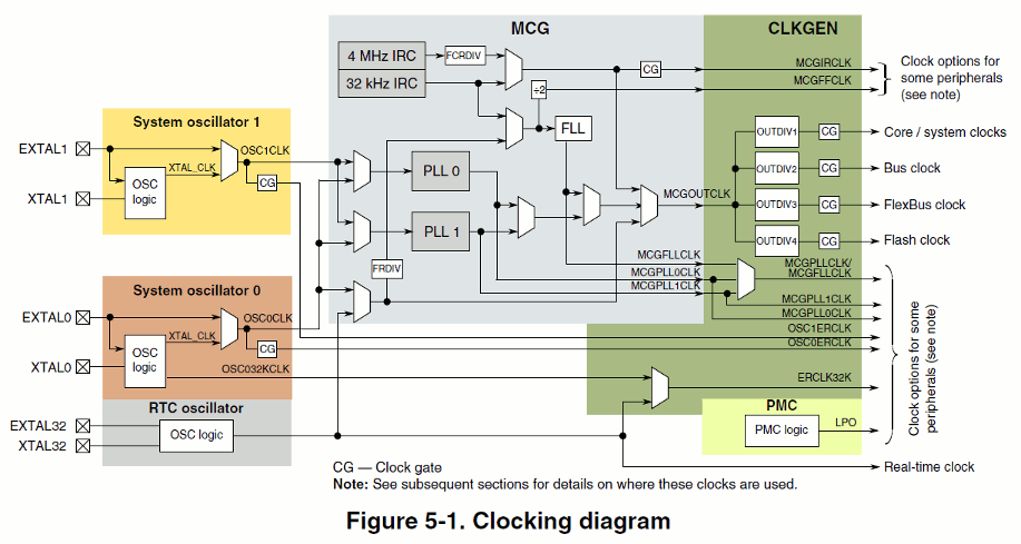
I'm attaching excerpt from Kinetis reference manual that may make situation clearer.
These MCG and SIM registers are used only to determine configuration (clock fixed rates and clock signal origins) at run time.
Namely, the real MCGOUTCLK source (in the middle) which is the parent for core clock (CCLK) and peripheral clock (PCLK) is determined at run time by reading MCG registers, let me quote commit message from Emcraft git repo:
* Determine in run-time what oscillator module (OSC0 or OSC1) is used
as clock source for the main PLL.
* When OSC1 is selected, assume its frequency to be 12 MHz on all
boards (there is a 12 MHz oscillator on XTAL1/EXTAL1 on K70-SOM and TWR-K70F120M boards).
In my .dts I'm trying to possibly follow real clock hierarchy, but to go anywhere behind MCGOUTCLK would require ability to rewrite .dtb e.g. by U-boot. But that's too demanding for any potential users of this BSP. So let's asume that MCGOUTCLK is the root clock and a parent for CCLK and PCLK.
In my most recent version I added OSC0ERCLK explicitly as one more root clock, since it is also used directly (through CG reg. 1 bit 0) by Freescale fec network device whose in-tree driver I'm trying to make usable for Kinetis.
Quoted 20 lines · Arnd Bergmann
Quoted 8 lines · On Friday 03 July 2015 00:08:27 Thomas Gleixner wrote:
Quoted 7 lines · Paul Osmialowski
Quoted 4 lines · Arnd Bergmann
I wonder if you could move out the fixed rate clocks into their own nodes. Are they actually controlled by the same block? If they are just fixed, you can use the normal binding for fixed rate clocks and only describe the clocks that are related to the driver.
Quoted 7 lines
Quoted 2 lines
In my view having these clocks grouped together looks more convincing. After all, they all share the same I/O regs in order to read configuration.
The fact that they share a register is not making them a group. That's just a HW design decision and you need to deal with that by protecting the register access, but not by trying to group them artificially at the functional level.
I'd disagree with that: The clock controller is the device that owns the registers and that should be one node in DT, as Paul's first version does.
Quoted 7 lines
The part I'm still struggling with is understanding how the fixed-rate clocks are controlled through those registers. If they are indeed configured through the registers, the name is probably wrong and should be changed to whatever kind of non-fixed clock this is.
Arnd
-------------- next part --------------
A non-text attachment was scrubbed...
Name: kinetis-clkgen.gif
Type: image/gif
Size: 57514 bytes
Desc:
URL: <http://lists.infradead.org/pipermail/linux-arm-kernel/attachments/20150704/ab0f010e/attachment-0001.gif>
Re: [PATCH v2 3/9] arm: twr-k70f120m: clock driver for Kinetis SoC
Hi Guys,
Let me share with you one more approach. I moved clocks back to sub-devices, so sharing the same resources (registers) is more obvious again. I like it better than previous approach. Can you look at this, please?
Quoted 23 lines · Paul Osmialowski
Hi Arnd,
I'm attaching excerpt from Kinetis reference manual that may make situation clearer.
These MCG and SIM registers are used only to determine configuration (clock fixed rates and clock signal origins) at run time.
Namely, the real MCGOUTCLK source (in the middle) which is the parent for core clock (CCLK) and peripheral clock (PCLK) is determined at run time by reading MCG registers, let me quote commit message from Emcraft git repo:
* Determine in run-time what oscillator module (OSC0 or OSC1) is used as clock source for the main PLL.
* When OSC1 is selected, assume its frequency to be 12 MHz on all boards (there is a 12 MHz oscillator on XTAL1/EXTAL1 on K70-SOM and TWR-K70F120M boards).In my .dts I'm trying to possibly follow real clock hierarchy, but to go anywhere behind MCGOUTCLK would require ability to rewrite .dtb e.g. by U-boot. But that's too demanding for any potential users of this BSP. So let's asume that MCGOUTCLK is the root clock and a parent for CCLK and PCLK.
Quoted 37 lines
In my most recent version I added OSC0ERCLK explicitly as one more root clock, since it is also used directly (through CG reg. 1 bit 0) by Freescale fec network device whose in-tree driver I'm trying to make usable for Kinetis.
Quoted 29 lines · Arnd Bergmann
Quoted 8 lines · On Friday 03 July 2015 00:08:27 Thomas Gleixner wrote:
Quoted 7 lines · Paul Osmialowski
Quoted 4 lines · Arnd Bergmann
I wonder if you could move out the fixed rate clocks into their own nodes. Are they actually controlled by the same block? If they are just fixed, you can use the normal binding for fixed rate clocks and only describe the clocks that are related to the driver.
Quoted 8 lines
Quoted 3 lines
In my view having these clocks grouped together looks more convincing. After
all, they all share the same I/O regs in order to read configuration.The fact that they share a register is not making them a group. That's just a HW design decision and you need to deal with that by protecting the register access, but not by trying to group them artificially at the functional level.
I'd disagree with that: The clock controller is the device that owns the registers and that should be one node in DT, as Paul's first version does.
The part I'm still struggling with is understanding how the fixed-rate clocks are controlled through those registers. If they are indeed configured
through the registers, the name is probably wrong and should be changed to whatever kind of non-fixed clock this is.Arnd
-------------- next part --------------
A non-text attachment was scrubbed...
Name: 0003-arm-twr-k70f120m-clock-driver-for-Kinetis-SoC.patch
Type: text/x-diff
Size: 20061 bytes
Desc:
URL: <http://lists.infradead.org/pipermail/linux-arm-kernel/attachments/20150706/1653224d/attachment-0001.bin>
Re: [PATCH v2 3/9] arm: twr-k70f120m: clock driver for Kinetis SoC
In reply to Paul OsmialowskiQuoting Paul Osmialowski (2015-07-04 14:50:03)
Quoted 4 lines
Hi Arnd,
I'm attaching excerpt from Kinetis reference manual that may make situation clearer.
Hi Paul,
Can you please post the patch in the body of the email instead of an attachment? It makes it easier to review. Another small nitpick is that the $SUBJECT for this patch might be better off as something like:
clk: mcg and sim clock drivers for twr-k70f120m Kinetis SoC
At least it helps me find the patch I care about when skimming the series ;-)
Quoted 10 lines
These MCG and SIM registers are used only to determine configuration (clock fixed rates and clock signal origins) at run time.
Namely, the real MCGOUTCLK source (in the middle) which is the parent for core clock (CCLK) and peripheral clock (PCLK) is determined at run time by reading MCG registers, let me quote commit message from Emcraft git repo:
* Determine in run-time what oscillator module (OSC0 or OSC1) is used
as clock source for the main PLL.
According to [0] there are three options: a 32k RTC osc clock and osc0 both feed into a mux. You should model this 32k clock with the fixed-rate binding.
Quoted 9 lines
* When OSC1 is selected, assume its frequency to be 12 MHz on all
boards (there is a 12 MHz oscillator on XTAL1/EXTAL1 on K70-SOM and TWR-K70F120M boards).In my .dts I'm trying to possibly follow real clock hierarchy, but to go anywhere behind MCGOUTCLK would require ability to rewrite .dtb e.g. by U-boot. But that's too demanding for any potential users of this BSP. So let's asume that MCGOUTCLK is the root clock and a parent for CCLK and PCLK.
I'm confused. The point of device tree is to solve problems like this; i.e. board-specific differences such as different oscillator frequencies.
OSC0 and OSC1 should each be a fixed-rate clock in your board-specific TWR-K70F120M DTS (not a chip-specific file). They do not belong in the cmu node, and they should use the "fixed-clock" binding. The 32k RTC osc can probably go in your chip-specific .dtsi as a fixed-rate clock since it appears to mandated in the reference manual[0].
These three fixed-rate clocks are your root clock nodes. Customers only need to worry about this if they spin a board, and then they will need to populate the frequencies of OSC0 and OSC1 in their board-specific .dts.
Please break clk-kinetis.c into two files:drivers/clk/kinetis/clk-mcg.cdrivers/clk/kinetis/clk-sim.c
Below is what your binding/dts should look like:
{
	osc0: clock {
		compatible = "fixed-clock";
		#clock-cells = <0>;
		clock-frequency = <50000000>;
	};

	osc1: clock {
		compatible = "fixed-clock";
		#clock-cells = <0>;
		clock-frequency = <12000000>;
	};

	rtc: clock {
		compatible = "fixed-clock";
		#clock-cells = <0>;
		clock-frequency = <32768>;
	};

	soc: soc {
		mcg: clock-controller at 40064000 {
			compatible = "fsl,kinetis-mcg";
			clock-cells = <1>;
			reg = <0x40064000 0x14>;
			clocks = <&osc0>, <&osc1>, <&rtc>;
			clock-names = "osc0", "osc1", "rtc";
		};

		sim: clock-controller at 40047000 {
			compatible = "fsl,kinetis-sim";
			clock-cells = <1>;
			reg = <0x40047000 0x1100>;
			clocks = <&mcg MCG_MCGOUTCLK_DIV1>, <&mcg MCG_MCGOUTCLK_DIV2>, <&mcg MCG_MCGOUTCLK_DIV3> <&mcg MCG_MCGOUTCLK_DIV4>;
			clock-names = "core", "bus", "flexbus", "flash";
		};
	};

	uart0: serial at 4006a000 {
		compatible = "fsl,kinetis-lpuart";
		reg = <0x4006a000 0x1000>;
		clocks = <&sim SIM_SCGC4_UART1_CLK>;
		clock-names = "gate";
	};
I removed the interrupts and dma stuff from the uart0 node for clarity. The above is the only style of binding that I have been accepting for some time; first declare the clock controller and establish its register space, and then consumers can consume clocks by providing the phandle to the controller plus an offset corresponding to a unique clock. The clock-names property makes it really easy to use with the clkdev stuff (e.g. clk_get()).
I've covered this before on the mailing list so here is a link describing how the qcom bindings do it in detail:
http://lkml.kernel.org/r/<20150416192014.19585.9663@quantum>
Technically you could encode the same bits as sub-nodes of the mcg and sim nodes, but the shared header is how the magic happens with the driver so it's best to keep the clock controller binding small and light.
I think this means you can also get rid of kinetis_of_clk_get_name and kinetis_clk_gate_get but my brain is tired so I'll leave that as an exercise to the reader.
[0] http://cache.freescale.com/files/microcontrollers/doc/ref_manual/K70P256M150SF3RM.pdf
Regards,
Mike
Quoted 40 lines
In my most recent version I added OSC0ERCLK explicitly as one more root clock, since it is also used directly (through CG reg. 1 bit 0) by Freescale fec network device whose in-tree driver I'm trying to make usable for Kinetis.
Quoted 20 lines · Arnd Bergmann
Quoted 8 lines · On Friday 03 July 2015 00:08:27 Thomas Gleixner wrote:
Quoted 7 lines · Paul Osmialowski
Quoted 4 lines · Arnd Bergmann
I wonder if you could move out the fixed rate clocks into their own nodes. Are they actually controlled by the same block? If they are just fixed, you can use the normal binding for fixed rate clocks and only describe the clocks that are related to the driver.
Quoted 7 lines
Quoted 2 lines
In my view having these clocks grouped together looks more convincing. After all, they all share the same I/O regs in order to read configuration.
The fact that they share a register is not making them a group. That's just a HW design decision and you need to deal with that by protecting the register access, but not by trying to group them artificially at the functional level.
I'd disagree with that: The clock controller is the device that owns the registers and that should be one node in DT, as Paul's first version does.
Quoted 7 lines
The part I'm still struggling with is understanding how the fixed-rate clocks are controlled through those registers. If they are indeed configured through the registers, the name is probably wrong and should be changed to whatever kind of non-fixed clock this is.
Arnd
_______________________________________________
linux-arm-kernel mailing list
linux-arm-kernel at lists.infradead.org
http://lists.infradead.org/mailman/listinfo/linux-arm-kernel
Re: [PATCH v2 3/9] arm: twr-k70f120m: clock driver for Kinetis SoC
Hi Mike,
Thank you for spending time on this and pointing me into the right direction. I'm wondering about going even further with it. Assuming that I know everything about my board, I can skip run-time discovery phase (note that the original driver was designed for other Kinetis-based boards too) and move everything into DTS, somewhat like this:
/ {
	osc0: clock {
		compatible = "fixed-clock";
		#clock-cells = <0>;
		clock-frequency = <50000000>;
	};

	osc1: clock {
		compatible = "fixed-clock";
		#clock-cells = <0>;
		clock-frequency = <12000000>;
	};

	rtc: clock {
		compatible = "fixed-clock";
		#clock-cells = <0>;
		clock-frequency = <32768>;
	};

	mcgout: clock {
		compatible = "fixed-factor-clock";
		#clock-cells = <0>;
		clocks = <&osc0>;
		clock-mult = <12>;
		clock-div = <5>;
	};

	core: clock {
		compatible = "fixed-factor-clock";
		#clock-cells = <0>;
		clocks = <&mcgout>;
		clock-mult = <1>;
		clock-div = <1>;
	};

	bus: clock {
		compatible = "fixed-factor-clock";
		#clock-cells = <0>;
		clocks = <&mcgout>;
		clock-mult = <1>;
		clock-div = <2>;
	};

	soc {
		cmu at 0x40047000 {
			compatible = "fsl,kinetis-gate-clock";
			reg = <0x40047000 0x1100>;

			mcg_core_gate: clock-gate {
				clocks = <&core>;
				#clock-cells = <2>;
			};

			mcg_bus_gate: clock-gate {
				clocks = <&bus>;
				#clock-cells = <2>;
			};

			osc0_erclk_gate: clock-gate {
				clocks = <&osc0>;
				#clock-cells = <2>;
			};
		};

		uart0: serial at 4006a000 {
			compatible = "fsl,kinetis-lpuart";
			reg = <0x4006a000 0x1000>;
			interrupts = <45>, <46>;
			interrupt-names = "uart-stat", "uart-err";
			clocks = <&mcg_core_gate 3 10>;
			clock-names = "ipg";
			dmas = <&edma 0 2>;
			dma-names = "rx";
			status = "disabled";
		};
	};
};
As you can see, mcg part is not required anymore.
I guess that the approach above would require split into soc-specific and board-specific part (as I said, dividers arrangement is something board specific), but I wonder what you thing about this proposal.
Thanks,
Paul
Quoted 175 lines · Michael Turquette
Quoting Paul Osmialowski (2015-07-04 14:50:03)
Quoted 4 lines
Hi Arnd,
I'm attaching excerpt from Kinetis reference manual that may make situation clearer.
Hi Paul,
Can you please post the patch in the body of the email instead of an attachment? It makes it easier to review. Another small nitpick is that the $SUBJECT for this patch might be better off as something like:
clk: mcg and sim clock drivers for twr-k70f120m Kinetis SoC
At least it helps me find the patch I care about when skimming the series ;-)
Quoted 10 lines
These MCG and SIM registers are used only to determine configuration (clock fixed rates and clock signal origins) at run time.
Namely, the real MCGOUTCLK source (in the middle) which is the parent for core clock (CCLK) and peripheral clock (PCLK) is determined at run time by reading MCG registers, let me quote commit message from Emcraft git repo:
* Determine in run-time what oscillator module (OSC0 or OSC1) is used
as clock source for the main PLL.According to [0] there are three options: a 32k RTC osc clock and osc0 both feed into a mux. You should model this 32k clock with the fixed-rate binding.
Quoted 9 lines
* When OSC1 is selected, assume its frequency to be 12 MHz on all
boards (there is a 12 MHz oscillator on XTAL1/EXTAL1 on K70-SOM and TWR-K70F120M boards).In my .dts I'm trying to possibly follow real clock hierarchy, but to go anywhere behind MCGOUTCLK would require ability to rewrite .dtb e.g. by U-boot. But that's too demanding for any potential users of this BSP. So let's asume that MCGOUTCLK is the root clock and a parent for CCLK and PCLK.
I'm confused. The point of device tree is to solve problems like this; i.e. board-specific differences such as different oscillator frequencies.
OSC0 and OSC1 should each be a fixed-rate clock in your board-specific TWR-K70F120M DTS (not a chip-specific file). They do not belong in the cmu node, and they should use the "fixed-clock" binding. The 32k RTC osc can probably go in your chip-specific .dtsi as a fixed-rate clock since it appears to mandated in the reference manual[0].
These three fixed-rate clocks are your root clock nodes. Customers only need to worry about this if they spin a board, and then they will need to populate the frequencies of OSC0 and OSC1 in their board-specific .dts.
Please break
clk-kinetis.cinto two files:drivers/clk/kinetis/clk-mcg.cdrivers/clk/kinetis/clk-sim.cBelow is what your binding/dts should look like:
{
	osc0: clock {
		compatible = "fixed-clock";
		#clock-cells = <0>;
		clock-frequency = <50000000>;
	};

	osc1: clock {
		compatible = "fixed-clock";
		#clock-cells = <0>;
		clock-frequency = <12000000>;
	};

	rtc: clock {
		compatible = "fixed-clock";
		#clock-cells = <0>;
		clock-frequency = <32768>;
	};

	soc: soc {
		mcg: clock-controller at 40064000 {
			compatible = "fsl,kinetis-mcg";
			clock-cells = <1>;
			reg = <0x40064000 0x14>;
			clocks = <&osc0>, <&osc1>, <&rtc>;
			clock-names = "osc0", "osc1", "rtc";
		};

		sim: clock-controller at 40047000 {
			compatible = "fsl,kinetis-sim";
			clock-cells = <1>;
			reg = <0x40047000 0x1100>;
			clocks = <&mcg MCG_MCGOUTCLK_DIV1>, <&mcg MCG_MCGOUTCLK_DIV2>, <&mcg MCG_MCGOUTCLK_DIV3> <&mcg MCG_MCGOUTCLK_DIV4>;
			clock-names = "core", "bus", "flexbus", "flash";
		};
	};

	uart0: serial at 4006a000 {
		compatible = "fsl,kinetis-lpuart";
		reg = <0x4006a000 0x1000>;
		clocks = <&sim SIM_SCGC4_UART1_CLK>;
		clock-names = "gate";
	};
I removed the interrupts and dma stuff from the uart0 node for clarity. The above is the only style of binding that I have been accepting for some time; first declare the clock controller and establish its register space, and then consumers can consume clocks by providing the phandle to the controller plus an offset corresponding to a unique clock. The clock-names property makes it really easy to use with the clkdev stuff (e.g.
clk_get()).I've covered this before on the mailing list so here is a link describing how the qcom bindings do it in detail:
http://lkml.kernel.org/r/<20150416192014.19585.9663@quantum>
Technically you could encode the same bits as sub-nodes of the mcg and sim nodes, but the shared header is how the magic happens with the driver so it's best to keep the clock controller binding small and light.
I think this means you can also get rid of
kinetis_of_clk_get_nameandkinetis_clk_gate_getbut my brain is tired so I'll leave that as an exercise to the reader.[0] http://cache.freescale.com/files/microcontrollers/doc/ref_manual/K70P256M150SF3RM.pdf
Regards,
MikeQuoted 40 lines
In my most recent version I added OSC0ERCLK explicitly as one more root clock, since it is also used directly (through CG reg. 1 bit 0) by Freescale fec network device whose in-tree driver I'm trying to make usable for Kinetis.
Quoted 20 lines · Arnd Bergmann
Quoted 8 lines · On Friday 03 July 2015 00:08:27 Thomas Gleixner wrote:
Quoted 7 lines · Paul Osmialowski
Quoted 4 lines · Arnd Bergmann
I wonder if you could move out the fixed rate clocks into their own nodes. Are they actually controlled by the same block? If they are just fixed, you can use the normal binding for fixed rate clocks and only describe the clocks that are related to the driver.
Quoted 7 lines
Quoted 2 lines
In my view having these clocks grouped together looks more convincing. After all, they all share the same I/O regs in order to read configuration.
The fact that they share a register is not making them a group. That's just a HW design decision and you need to deal with that by protecting the register access, but not by trying to group them artificially at the functional level.
I'd disagree with that: The clock controller is the device that owns the registers and that should be one node in DT, as Paul's first version does.
Quoted 7 lines
The part I'm still struggling with is understanding how the fixed-rate clocks are controlled through those registers. If they are indeed configured through the registers, the name is probably wrong and should be changed to whatever kind of non-fixed clock this is.
Arnd
_______________________________________________
linux-arm-kernel mailing list
linux-arm-kernel at lists.infradead.org
http://lists.infradead.org/mailman/listinfo/linux-arm-kernel
PATCH v2 3/9 arm: twr-k70f120m: clock driver for Kinetis SoC
Quoting Paul Osmialowski (2015-07-26 13:24:08)
Quoted 4 lines
Hi Mike,
Thank you for spending time on this and pointing me into the right direction. I'm wondering about going even further with it. Assuming that I
Hi Paul,
No problem! And thanks for the quick turnaround on your patches so far.
Quoted 23 lines
know everything about my board, I can skip run-time discovery phase (note that the original driver was designed for other Kinetis-based boards too) and move everything into DTS, somewhat like this:
/ {
        osc0: clock {
                compatible = "fixed-clock";
                #clock-cells = <0>;
                clock-frequency = <50000000>;
        };

        osc1: clock {
                compatible = "fixed-clock";
                #clock-cells = <0>;
                clock-frequency = <12000000>;
        };

        rtc: clock {
                compatible = "fixed-clock";
                #clock-cells = <0>;
                clock-frequency = <32768>;
        };
Quoted 7 lines
        mcgout: clock {
                compatible = "fixed-factor-clock";
                #clock-cells = <0>;
                clocks = <&osc0>;
                clock-mult = <12>;
                clock-div = <5>;
        };
I think this is a step backwards.
Did you look at the qcom clock binding and read the email where I detailed how that binding works?
The point of that type of binding is to not shove per-clock data into DT, but instead to declare every clock controller IP block (e.g. the device) as well as every board-level clock (e.g. as osc that feeds into your mcu). Once these "clock providers" are enumerated in DT, then we create linkage between the clock providers and the clock consumers by using phandles + an index. Linux device drivers tap into this by using clk_get() and using the "clock-names" property from DT.
Put another way: we mostly use DT to model "devices". That is open to interpretation for but for clock-related stuff we typically interpret the clock controller as the device, not the individual clock outputs coming out of the controller.
Note that a clock controller IP block may be both a provider and a consumer. I/O controllers are a very common type of consumer (e.g. USB host controller, MMC controller, GPU, etc).
Additionally, from my reading of the reference manual, mcgout is defined as:
"""
MCG output of either IRC, MCGFLLCLK MCGPLL0CLK, MCGPLL1CLK, or MCG's external reference clock that sources the core, system, bus, FlexBus, and flash clock. It is also an option for the debug trace clock.
"""
So why is it listed here as a fixed-factor clock? Is it not a multiplexer? Also, why is it listed here at all? Please take another look at the qcom binding example I linked to in my previous mail.
Quoted 15 lines
        core: clock {
                compatible = "fixed-factor-clock";
                #clock-cells = <0>;
                clocks = <&mcgout>;
                clock-mult = <1>;
                clock-div = <1>;
        };

        bus: clock {
                compatible = "fixed-factor-clock";
                #clock-cells = <0>;
                clocks = <&mcgout>;
                clock-mult = <1>;
                clock-div = <2>;
These are actually not fixed dividers but programmable dividers. You can probably use drivers/clk/clk-divider.c for these. I'm fine with using fixed-dividers for the initial merge just to get things up and running if that is your strategy, but you'll need to revisit them later on when you need more flexible support for other boards.
Again, I'm not sure why these clocks are enumerated in DT. Why not just enumerate your mcg clock controller and your sim clock controller? If you want to be a perfectionist then it appears that there is an osc clock controller upstream from the mcg controller as well ;-)
It occurs to me that maybe you are trying to use fixed-factor clocks so that you can program a sane default rate? We use the assigned-clock-rates property for that. Note that this value is a property of some device which *consumes* the clock, not the clock controller or the clock output itself.
Quoted 21 lines
        };

        soc {
                cmu at 0x40047000 {
                        compatible = "fsl,kinetis-gate-clock";
                        reg = <0x40047000 0x1100>;

                        mcg_core_gate: clock-gate {
                                clocks = <&core>;
                                #clock-cells = <2>;
                        };

                        mcg_bus_gate: clock-gate {
                                clocks = <&bus>;
                                #clock-cells = <2>;
                        };

                        osc0_erclk_gate: clock-gate {
                                clocks = <&osc0>;
                                #clock-cells = <2>;
                        };
Quoted 8 lines
                };

                uart0: serial at 4006a000 {
                        compatible = "fsl,kinetis-lpuart";
                        reg = <0x4006a000 0x1000>;
                        interrupts = <45>, <46>;
                        interrupt-names = "uart-stat", "uart-err";
                        clocks = <&mcg_core_gate 3 10>;
Magic numbers are not good. dtc has been able to use preprocessor macros for a while now which means we can use constants instead of magic numbers. Please look at the shared header in the qcom binding for an example.
Quoted 9 lines
                        clock-names = "ipg";
                        dmas = <&edma 0 2>;
                        dma-names = "rx";
                        status = "disabled";
                };
        };
};
As you can see, mcg part is not required anymore.
I think the mcg should be required. The mcg is a real IP block on your SoC, according to my reading of your technical reference manual. Just because you can model a few of its output clocks in dts does not mean that you should.
I did a quick grep and didn't find "cmu" anywhere in the reference manual.
Quoted 4 lines
I guess that the approach above would require split into soc-specific and board-specific part (as I said, dividers arrangement is something board specific), but I wonder what you thing about this proposal.
Splitting is good. Chip-specific stuff can go into the chip-specific dtsi file. The board-level (osc) stuff can go into the individual board files. The ultimate goal is to make it trivial to add new boards.
Regards,
Mike
Quoted 186 lines
Thanks,
PaulQuoted 125 lines · Michael Turquette
Quoting Paul Osmialowski (2015-07-04 14:50:03)
Quoted 4 lines
Hi Arnd,
I'm attaching excerpt from Kinetis reference manual that may make situation clearer.
Hi Paul,
Can you please post the patch in the body of the email instead of an attachment? It makes it easier to review. Another small nitpick is that the $SUBJECT for this patch might be better off as something like:
clk: mcg and sim clock drivers for twr-k70f120m Kinetis SoC
At least it helps me find the patch I care about when skimming the series ;-)
Quoted 10 lines
These MCG and SIM registers are used only to determine configuration (clock fixed rates and clock signal origins) at run time.
Namely, the real MCGOUTCLK source (in the middle) which is the parent for core clock (CCLK) and peripheral clock (PCLK) is determined at run time by reading MCG registers, let me quote commit message from Emcraft git repo:
* Determine in run-time what oscillator module (OSC0 or OSC1) is used
as clock source for the main PLL.According to [0] there are three options: a 32k RTC osc clock and osc0 both feed into a mux. You should model this 32k clock with the fixed-rate binding.
Quoted 9 lines
* When OSC1 is selected, assume its frequency to be 12 MHz on all
boards (there is a 12 MHz oscillator on XTAL1/EXTAL1 on K70-SOM and TWR-K70F120M boards).In my .dts I'm trying to possibly follow real clock hierarchy, but to go anywhere behind MCGOUTCLK would require ability to rewrite .dtb e.g. by U-boot. But that's too demanding for any potential users of this BSP. So let's asume that MCGOUTCLK is the root clock and a parent for CCLK and PCLK.
I'm confused. The point of device tree is to solve problems like this; i.e. board-specific differences such as different oscillator frequencies.
OSC0 and OSC1 should each be a fixed-rate clock in your board-specific TWR-K70F120M DTS (not a chip-specific file). They do not belong in the cmu node, and they should use the "fixed-clock" binding. The 32k RTC osc can probably go in your chip-specific .dtsi as a fixed-rate clock since it appears to mandated in the reference manual[0].
These three fixed-rate clocks are your root clock nodes. Customers only need to worry about this if they spin a board, and then they will need to populate the frequencies of OSC0 and OSC1 in their board-specific .dts.
Please break
clk-kinetis.cinto two files:drivers/clk/kinetis/clk-mcg.cdrivers/clk/kinetis/clk-sim.cBelow is what your binding/dts should look like:
{
      osc0: clock {
              compatible = "fixed-clock";
              #clock-cells = <0>;
              clock-frequency = <50000000>;
      };

      osc1: clock {
              compatible = "fixed-clock";
              #clock-cells = <0>;
              clock-frequency = <12000000>;
      };

      rtc: clock {
              compatible = "fixed-clock";
              #clock-cells = <0>;
              clock-frequency = <32768>;
      };

      soc: soc {
              mcg: clock-controller at 40064000 {
                      compatible = "fsl,kinetis-mcg";
                      clock-cells = <1>;
                      reg = <0x40064000 0x14>;
                      clocks = <&osc0>, <&osc1>, <&rtc>;
                      clock-names = "osc0", "osc1", "rtc";
              };

              sim: clock-controller at 40047000 {
                      compatible = "fsl,kinetis-sim";
                      clock-cells = <1>;
                      reg = <0x40047000 0x1100>;
                      clocks = <&mcg MCG_MCGOUTCLK_DIV1>, <&mcg MCG_MCGOUTCLK_DIV2>, <&mcg MCG_MCGOUTCLK_DIV3> <&mcg MCG_MCGOUTCLK_DIV4>;
                      clock-names = "core", "bus", "flexbus", "flash";
              };
      };

      uart0: serial at 4006a000 {
              compatible = "fsl,kinetis-lpuart";
              reg = <0x4006a000 0x1000>;
              clocks = <&sim SIM_SCGC4_UART1_CLK>;
              clock-names = "gate";
      };
I removed the interrupts and dma stuff from the uart0 node for clarity. The above is the only style of binding that I have been accepting for some time; first declare the clock controller and establish its register space, and then consumers can consume clocks by providing the phandle to the controller plus an offset corresponding to a unique clock. The clock-names property makes it really easy to use with the clkdev stuff (e.g.
clk_get()).I've covered this before on the mailing list so here is a link describing how the qcom bindings do it in detail:
http://lkml.kernel.org/r/<20150416192014.19585.9663@quantum>
Technically you could encode the same bits as sub-nodes of the mcg and sim nodes, but the shared header is how the magic happens with the driver so it's best to keep the clock controller binding small and light.
Quoted 50 lines
I think this means you can also get rid of
kinetis_of_clk_get_nameandkinetis_clk_gate_getbut my brain is tired so I'll leave that as an exercise to the reader.[0] http://cache.freescale.com/files/microcontrollers/doc/ref_manual/K70P256M150SF3RM.pdf
Regards,
MikeQuoted 40 lines
In my most recent version I added OSC0ERCLK explicitly as one more root clock, since it is also used directly (through CG reg. 1 bit 0) by Freescale fec network device whose in-tree driver I'm trying to make usable for Kinetis.
Quoted 20 lines · Arnd Bergmann
Quoted 8 lines · On Friday 03 July 2015 00:08:27 Thomas Gleixner wrote:
Quoted 7 lines · Paul Osmialowski
Quoted 4 lines · Arnd Bergmann
I wonder if you could move out the fixed rate clocks into their own nodes. Are they actually controlled by the same block? If they are just fixed, you can use the normal binding for fixed rate clocks and only describe the clocks that are related to the driver.
Quoted 7 lines
Quoted 2 lines
In my view having these clocks grouped together looks more convincing. After all, they all share the same I/O regs in order to read configuration.
The fact that they share a register is not making them a group. That's just a HW design decision and you need to deal with that by protecting the register access, but not by trying to group them artificially at the functional level.
I'd disagree with that: The clock controller is the device that owns the registers and that should be one node in DT, as Paul's first version does.
Quoted 7 lines
The part I'm still struggling with is understanding how the fixed-rate clocks are controlled through those registers. If they are indeed configured through the registers, the name is probably wrong and should be changed to whatever kind of non-fixed clock this is.
Arnd
_______________________________________________
linux-arm-kernel mailing list
linux-arm-kernel at lists.infradead.org
http://lists.infradead.org/mailman/listinfo/linux-arm-kernel--
To unsubscribe from this list: send the line "unsubscribe linux-kernel" in the body of a message to majordomo at vger.kernel.org
More majordomo info at http://vger.kernel.org/majordomo-info.html
Please read the FAQ at http://www.tux.org/lkml/
Re: [PATCH v2 3/9] arm: twr-k70f120m: clock driver for Kinetis SoC
Hi Mike,
My trouble is that now I'm dealing with two conradictory opinions on how this driver should be written. The one you presented in your previous post assumes that there will be a header file with defines shared between the clock driver and DTS, also with clock gating details hidden behind some additional level of indirection, e.g.:
clocks = <&sim SIM_SCGC4_UART1_CLK>;
Note that I've been through this at the very beginning, though the names I used have been bit different, e.g.:
#define KINETIS_CG_UART1 KINETIS_MKCG(3, 11) /* SIM_SCGC4[11] */
This was rejected with a comment by Arnd:
Instead of using a triple indirection here, just put the tuples in the DT directly using #clock-cells=<2>, and get rid of both this header file and the dt-bindings/clock/kinetis-mcg.h file.
So I dropped all of these includes and started to use magic numbers (as you put it). Now I need to go one way or another or even go the third way:
extend #clock-cells to <3> and address it like: <&sim parent_clock_id scgc_register_number bit_index_number>.
Reading your previous post I'm starting to feel that it would bring me closer to final acceptance if I stick to what you proposed in that post (I'm really grateful to you for writting so huge chunk of DTS for me!), so I'll probably adopt that.
You're right about my "get things up and running" attitude - currently I want to develop things extensively (cover as much subsystems as possible) and then at some stage switch to intensive approach. This board is a somewhat huge monster (for a Cortex-M4 SoC) and there will be a lot of coding opportunity in this field in the future.
Thanks,
Paul
Quoted 362 lines · Michael Turquette
Quoting Paul Osmialowski (2015-07-26 13:24:08)
Quoted 4 lines
Hi Mike,
Thank you for spending time on this and pointing me into the right direction. I'm wondering about going even further with it. Assuming that I
Hi Paul,
No problem! And thanks for the quick turnaround on your patches so far.
Quoted 23 lines
know everything about my board, I can skip run-time discovery phase (note that the original driver was designed for other Kinetis-based boards too) and move everything into DTS, somewhat like this:
/ {
        osc0: clock {
                compatible = "fixed-clock";
                #clock-cells = <0>;
                clock-frequency = <50000000>;
        };

        osc1: clock {
                compatible = "fixed-clock";
                #clock-cells = <0>;
                clock-frequency = <12000000>;
        };

        rtc: clock {
                compatible = "fixed-clock";
                #clock-cells = <0>;
                clock-frequency = <32768>;
        };
Quoted 7 lines
        mcgout: clock {
                compatible = "fixed-factor-clock";
                #clock-cells = <0>;
                clocks = <&osc0>;
                clock-mult = <12>;
                clock-div = <5>;
        };
I think this is a step backwards.
Did you look at the qcom clock binding and read the email where I detailed how that binding works?
The point of that type of binding is to not shove per-clock data into DT, but instead to declare every clock controller IP block (e.g. the device) as well as every board-level clock (e.g. as osc that feeds into your mcu). Once these "clock providers" are enumerated in DT, then we create linkage between the clock providers and the clock consumers by using phandles + an index. Linux device drivers tap into this by using
clk_get()and using the "clock-names" property from DT.Put another way: we mostly use DT to model "devices". That is open to interpretation for but for clock-related stuff we typically interpret the clock controller as the device, not the individual clock outputs coming out of the controller.
Note that a clock controller IP block may be both a provider and a consumer. I/O controllers are a very common type of consumer (e.g. USB host controller, MMC controller, GPU, etc).
Additionally, from my reading of the reference manual, mcgout is defined as:
"""
MCG output of either IRC, MCGFLLCLK MCGPLL0CLK, MCGPLL1CLK, or MCG's external reference clock that sources the core, system, bus, FlexBus, and flash clock. It is also an option for the debug trace clock.
"""So why is it listed here as a fixed-factor clock? Is it not a multiplexer? Also, why is it listed here at all? Please take another look at the qcom binding example I linked to in my previous mail.
Quoted 15 lines
        core: clock {
                compatible = "fixed-factor-clock";
                #clock-cells = <0>;
                clocks = <&mcgout>;
                clock-mult = <1>;
                clock-div = <1>;
        };

        bus: clock {
                compatible = "fixed-factor-clock";
                #clock-cells = <0>;
                clocks = <&mcgout>;
                clock-mult = <1>;
                clock-div = <2>;
These are actually not fixed dividers but programmable dividers. You can probably use
drivers/clk/clk-divider.cfor these. I'm fine with using fixed-dividers for the initial merge just to get things up and running if that is your strategy, but you'll need to revisit them later on when you need more flexible support for other boards.Again, I'm not sure why these clocks are enumerated in DT. Why not just enumerate your mcg clock controller and your sim clock controller? If you want to be a perfectionist then it appears that there is an osc clock controller upstream from the mcg controller as well ;-)
It occurs to me that maybe you are trying to use fixed-factor clocks so that you can program a sane default rate? We use the assigned-clock-rates property for that. Note that this value is a property of some device which *consumes* the clock, not the clock controller or the clock output itself.
Quoted 21 lines
        };

        soc {
                cmu at 0x40047000 {
                        compatible = "fsl,kinetis-gate-clock";
                        reg = <0x40047000 0x1100>;

                        mcg_core_gate: clock-gate {
                                clocks = <&core>;
                                #clock-cells = <2>;
                        };

                        mcg_bus_gate: clock-gate {
                                clocks = <&bus>;
                                #clock-cells = <2>;
                        };

                        osc0_erclk_gate: clock-gate {
                                clocks = <&osc0>;
                                #clock-cells = <2>;
                        };
Quoted 8 lines
                };

                uart0: serial at 4006a000 {
                        compatible = "fsl,kinetis-lpuart";
                        reg = <0x4006a000 0x1000>;
                        interrupts = <45>, <46>;
                        interrupt-names = "uart-stat", "uart-err";
                        clocks = <&mcg_core_gate 3 10>;
Magic numbers are not good. dtc has been able to use preprocessor macros for a while now which means we can use constants instead of magic numbers. Please look at the shared header in the qcom binding for an example.
Quoted 9 lines
                        clock-names = "ipg";
                        dmas = <&edma 0 2>;
                        dma-names = "rx";
                        status = "disabled";
                };
        };
};
As you can see, mcg part is not required anymore.
I think the mcg should be required. The mcg is a real IP block on your SoC, according to my reading of your technical reference manual. Just because you can model a few of its output clocks in dts does not mean that you should.
I did a quick grep and didn't find "cmu" anywhere in the reference manual.
Quoted 4 lines
I guess that the approach above would require split into soc-specific and board-specific part (as I said, dividers arrangement is something board specific), but I wonder what you thing about this proposal.
Splitting is good. Chip-specific stuff can go into the chip-specific dtsi file. The board-level (osc) stuff can go into the individual board files. The ultimate goal is to make it trivial to add new boards.
Regards,
MikeQuoted 186 lines
Thanks,
PaulQuoted 125 lines · Michael Turquette
Quoting Paul Osmialowski (2015-07-04 14:50:03)
Quoted 4 lines
Hi Arnd,
I'm attaching excerpt from Kinetis reference manual that may make situation clearer.
Hi Paul,
Can you please post the patch in the body of the email instead of an attachment? It makes it easier to review. Another small nitpick is that the $SUBJECT for this patch might be better off as something like:
clk: mcg and sim clock drivers for twr-k70f120m Kinetis SoC
At least it helps me find the patch I care about when skimming the series ;-)
Quoted 10 lines
These MCG and SIM registers are used only to determine configuration (clock fixed rates and clock signal origins) at run time.
Namely, the real MCGOUTCLK source (in the middle) which is the parent for core clock (CCLK) and peripheral clock (PCLK) is determined at run time by reading MCG registers, let me quote commit message from Emcraft git repo:
* Determine in run-time what oscillator module (OSC0 or OSC1) is used
as clock source for the main PLL.According to [0] there are three options: a 32k RTC osc clock and osc0 both feed into a mux. You should model this 32k clock with the fixed-rate binding.
Quoted 9 lines
* When OSC1 is selected, assume its frequency to be 12 MHz on all
boards (there is a 12 MHz oscillator on XTAL1/EXTAL1 on K70-SOM and TWR-K70F120M boards).In my .dts I'm trying to possibly follow real clock hierarchy, but to go anywhere behind MCGOUTCLK would require ability to rewrite .dtb e.g. by U-boot. But that's too demanding for any potential users of this BSP. So let's asume that MCGOUTCLK is the root clock and a parent for CCLK and PCLK.
I'm confused. The point of device tree is to solve problems like this; i.e. board-specific differences such as different oscillator frequencies.
OSC0 and OSC1 should each be a fixed-rate clock in your board-specific TWR-K70F120M DTS (not a chip-specific file). They do not belong in the cmu node, and they should use the "fixed-clock" binding. The 32k RTC osc can probably go in your chip-specific .dtsi as a fixed-rate clock since it appears to mandated in the reference manual[0].
These three fixed-rate clocks are your root clock nodes. Customers only need to worry about this if they spin a board, and then they will need to populate the frequencies of OSC0 and OSC1 in their board-specific .dts.
Please break
clk-kinetis.cinto two files:drivers/clk/kinetis/clk-mcg.cdrivers/clk/kinetis/clk-sim.cBelow is what your binding/dts should look like:
{
      osc0: clock {
              compatible = "fixed-clock";
              #clock-cells = <0>;
              clock-frequency = <50000000>;
      };

      osc1: clock {
              compatible = "fixed-clock";
              #clock-cells = <0>;
              clock-frequency = <12000000>;
      };

      rtc: clock {
              compatible = "fixed-clock";
              #clock-cells = <0>;
              clock-frequency = <32768>;
      };

      soc: soc {
              mcg: clock-controller at 40064000 {
                      compatible = "fsl,kinetis-mcg";
                      clock-cells = <1>;
                      reg = <0x40064000 0x14>;
                      clocks = <&osc0>, <&osc1>, <&rtc>;
                      clock-names = "osc0", "osc1", "rtc";
              };

              sim: clock-controller at 40047000 {
                      compatible = "fsl,kinetis-sim";
                      clock-cells = <1>;
                      reg = <0x40047000 0x1100>;
                      clocks = <&mcg MCG_MCGOUTCLK_DIV1>, <&mcg MCG_MCGOUTCLK_DIV2>, <&mcg MCG_MCGOUTCLK_DIV3> <&mcg MCG_MCGOUTCLK_DIV4>;
                      clock-names = "core", "bus", "flexbus", "flash";
              };
      };

      uart0: serial at 4006a000 {
              compatible = "fsl,kinetis-lpuart";
              reg = <0x4006a000 0x1000>;
              clocks = <&sim SIM_SCGC4_UART1_CLK>;
              clock-names = "gate";
      };
I removed the interrupts and dma stuff from the uart0 node for clarity. The above is the only style of binding that I have been accepting for some time; first declare the clock controller and establish its register space, and then consumers can consume clocks by providing the phandle to the controller plus an offset corresponding to a unique clock. The clock-names property makes it really easy to use with the clkdev stuff (e.g.
clk_get()).I've covered this before on the mailing list so here is a link describing how the qcom bindings do it in detail:
http://lkml.kernel.org/r/<20150416192014.19585.9663@quantum>
Technically you could encode the same bits as sub-nodes of the mcg and sim nodes, but the shared header is how the magic happens with the driver so it's best to keep the clock controller binding small and light.
Quoted 50 lines
I think this means you can also get rid of
kinetis_of_clk_get_nameandkinetis_clk_gate_getbut my brain is tired so I'll leave that as an exercise to the reader.[0] http://cache.freescale.com/files/microcontrollers/doc/ref_manual/K70P256M150SF3RM.pdf
Regards,
MikeQuoted 40 lines
In my most recent version I added OSC0ERCLK explicitly as one more root clock, since it is also used directly (through CG reg. 1 bit 0) by Freescale fec network device whose in-tree driver I'm trying to make usable for Kinetis.
Quoted 20 lines · Arnd Bergmann
Quoted 8 lines · On Friday 03 July 2015 00:08:27 Thomas Gleixner wrote:
Quoted 7 lines · Paul Osmialowski
Quoted 4 lines · Arnd Bergmann
I wonder if you could move out the fixed rate clocks into their own nodes. Are they actually controlled by the same block? If they are just fixed, you can use the normal binding for fixed rate clocks and only describe the clocks that are related to the driver.
Quoted 7 lines
Quoted 2 lines
In my view having these clocks grouped together looks more convincing. After all, they all share the same I/O regs in order to read configuration.
The fact that they share a register is not making them a group. That's just a HW design decision and you need to deal with that by protecting the register access, but not by trying to group them artificially at the functional level.
I'd disagree with that: The clock controller is the device that owns the registers and that should be one node in DT, as Paul's first version does.
Quoted 7 lines
The part I'm still struggling with is understanding how the fixed-rate clocks are controlled through those registers. If they are indeed configured through the registers, the name is probably wrong and should be changed to whatever kind of non-fixed clock this is.
Arnd
_______________________________________________
linux-arm-kernel mailing list
linux-arm-kernel at lists.infradead.org
http://lists.infradead.org/mailman/listinfo/linux-arm-kernel--
To unsubscribe from this list: send the line "unsubscribe linux-kernel" in the body of a message to majordomo at vger.kernel.org
More majordomo info at http://vger.kernel.org/majordomo-info.html
Please read the FAQ at http://www.tux.org/lkml/
PATCH v2 3/9 arm: twr-k70f120m: clock driver for Kinetis SoC
Quoting Paul Osmialowski (2015-07-28 13:30:17)
Quoted 13 lines
Hi Mike,
My trouble is that now I'm dealing with two conradictory opinions on how this driver should be written. The one you presented in your previous post assumes that there will be a header file with defines shared between the clock driver and DTS, also with clock gating details hidden behind some additional level of indirection, e.g.:
clocks = <&sim
SIM_SCGC4_UART1_CLK>;Note that I've been through this at the very beginning, though the names I used have been bit different, e.g.:
Quoted 7 lines
#define
KINETIS_CG_UART1KINETIS_MKCG(3, 11)/* SIM_SCGC4[11] */This was rejected with a comment by Arnd:
Instead of using a triple indirection here, just put the tuples in the DT directly using #clock-cells=<2>, and get rid of both this header file and the
dt-bindings/clock/kinetis-mcg.hfile.
Arnd, are you OK with my type of binding description now that I explained it with some examples?
Quoted 5 lines
So I dropped all of these includes and started to use magic numbers (as you put it). Now I need to go one way or another or even go the third way:
extend #clock-cells to <3> and address it like: <&simparent_clock_idscgc_register_numberbit_index_number>.
Paul,
Quoted 1 line
From my understanding the DT folks do not like register-level or
bit-level details going into DT. It is better to handle the clock signals as abstract resources and link a provider and consumer with a simple phandle plus an index representing that abstract resource (i.e. the clock output signal).
Quoted 11 lines
Reading your previous post I'm starting to feel that it would bring me closer to final acceptance if I stick to what you proposed in that post (I'm really grateful to you for writting so huge chunk of DTS for me!), so I'll probably adopt that.
You're right about my "get things up and running" attitude - currently I want to develop things extensively (cover as much subsystems as possible) and then at some stage switch to intensive approach. This board is a somewhat huge monster (for a Cortex-M4 SoC) and there will be a lot of coding opportunity in this field in the future.
I'm happy to take clock drivers and add my Reviewed-by to .dts files that make use of fixed-rate and fixed-factor clocks as an interim solution. Of course it will be best to get The Real Thing merged upstream asap, but this is something I've done before to help get new platform upstream before and I'm fine to do it again.
With that said, Devicetree bindings are allegedly a stable ABI that cannot be broken. So let's make sure that any Kinetis clock binding description is in good shape before merging it. The rest can follow on later if it needs to.
Regards,
Mike
Quoted 373 lines
Thanks,
PaulQuoted 168 lines · Michael Turquette
Quoting Paul Osmialowski (2015-07-26 13:24:08)
Quoted 4 lines
Hi Mike,
Thank you for spending time on this and pointing me into the right direction. I'm wondering about going even further with it. Assuming that I
Hi Paul,
No problem! And thanks for the quick turnaround on your patches so far.
Quoted 23 lines
know everything about my board, I can skip run-time discovery phase (note that the original driver was designed for other Kinetis-based boards too) and move everything into DTS, somewhat like this:
/ {
        osc0: clock {
                compatible = "fixed-clock";
                #clock-cells = <0>;
                clock-frequency = <50000000>;
        };

        osc1: clock {
                compatible = "fixed-clock";
                #clock-cells = <0>;
                clock-frequency = <12000000>;
        };

        rtc: clock {
                compatible = "fixed-clock";
                #clock-cells = <0>;
                clock-frequency = <32768>;
        };
Quoted 7 lines
        mcgout: clock {
                compatible = "fixed-factor-clock";
                #clock-cells = <0>;
                clocks = <&osc0>;
                clock-mult = <12>;
                clock-div = <5>;
        };
I think this is a step backwards.
Did you look at the qcom clock binding and read the email where I detailed how that binding works?
The point of that type of binding is to not shove per-clock data into DT, but instead to declare every clock controller IP block (e.g. the device) as well as every board-level clock (e.g. as osc that feeds into your mcu). Once these "clock providers" are enumerated in DT, then we create linkage between the clock providers and the clock consumers by using phandles + an index. Linux device drivers tap into this by using
clk_get()and using the "clock-names" property from DT.Put another way: we mostly use DT to model "devices". That is open to interpretation for but for clock-related stuff we typically interpret the clock controller as the device, not the individual clock outputs coming out of the controller.
Note that a clock controller IP block may be both a provider and a consumer. I/O controllers are a very common type of consumer (e.g. USB host controller, MMC controller, GPU, etc).
Additionally, from my reading of the reference manual, mcgout is defined as:
"""
MCG output of either IRC, MCGFLLCLK MCGPLL0CLK, MCGPLL1CLK, or MCG's external reference clock that sources the core, system, bus, FlexBus, and flash clock. It is also an option for the debug trace clock.
"""So why is it listed here as a fixed-factor clock? Is it not a multiplexer? Also, why is it listed here at all? Please take another look at the qcom binding example I linked to in my previous mail.
Quoted 15 lines
        core: clock {
                compatible = "fixed-factor-clock";
                #clock-cells = <0>;
                clocks = <&mcgout>;
                clock-mult = <1>;
                clock-div = <1>;
        };

        bus: clock {
                compatible = "fixed-factor-clock";
                #clock-cells = <0>;
                clocks = <&mcgout>;
                clock-mult = <1>;
                clock-div = <2>;
These are actually not fixed dividers but programmable dividers. You can probably use
drivers/clk/clk-divider.cfor these. I'm fine with using fixed-dividers for the initial merge just to get things up and running if that is your strategy, but you'll need to revisit them later on when you need more flexible support for other boards.Again, I'm not sure why these clocks are enumerated in DT. Why not just enumerate your mcg clock controller and your sim clock controller? If you want to be a perfectionist then it appears that there is an osc clock controller upstream from the mcg controller as well ;-)
It occurs to me that maybe you are trying to use fixed-factor clocks so that you can program a sane default rate? We use the assigned-clock-rates property for that. Note that this value is a property of some device which *consumes* the clock, not the clock controller or the clock output itself.
Quoted 21 lines
        };

        soc {
                cmu at 0x40047000 {
                        compatible = "fsl,kinetis-gate-clock";
                        reg = <0x40047000 0x1100>;

                        mcg_core_gate: clock-gate {
                                clocks = <&core>;
                                #clock-cells = <2>;
                        };

                        mcg_bus_gate: clock-gate {
                                clocks = <&bus>;
                                #clock-cells = <2>;
                        };

                        osc0_erclk_gate: clock-gate {
                                clocks = <&osc0>;
                                #clock-cells = <2>;
                        };
Quoted 8 lines
                };

                uart0: serial at 4006a000 {
                        compatible = "fsl,kinetis-lpuart";
                        reg = <0x4006a000 0x1000>;
                        interrupts = <45>, <46>;
                        interrupt-names = "uart-stat", "uart-err";
                        clocks = <&mcg_core_gate 3 10>;
Magic numbers are not good. dtc has been able to use preprocessor macros for a while now which means we can use constants instead of magic numbers. Please look at the shared header in the qcom binding for an example.
Quoted 9 lines
                        clock-names = "ipg";
                        dmas = <&edma 0 2>;
                        dma-names = "rx";
                        status = "disabled";
                };
        };
};
As you can see, mcg part is not required anymore.
I think the mcg should be required. The mcg is a real IP block on your SoC, according to my reading of your technical reference manual. Just because you can model a few of its output clocks in dts does not mean that you should.
I did a quick grep and didn't find "cmu" anywhere in the reference manual.
Quoted 4 lines
I guess that the approach above would require split into soc-specific and board-specific part (as I said, dividers arrangement is something board specific), but I wonder what you thing about this proposal.
Quoted 194 lines
Splitting is good. Chip-specific stuff can go into the chip-specific dtsi file. The board-level (osc) stuff can go into the individual board files. The ultimate goal is to make it trivial to add new boards.
Regards,
MikeQuoted 186 lines
Thanks,
PaulQuoted 125 lines · Michael Turquette
Quoting Paul Osmialowski (2015-07-04 14:50:03)
Quoted 4 lines
Hi Arnd,
I'm attaching excerpt from Kinetis reference manual that may make situation clearer.
Hi Paul,
Can you please post the patch in the body of the email instead of an attachment? It makes it easier to review. Another small nitpick is that the $SUBJECT for this patch might be better off as something like:
clk: mcg and sim clock drivers for twr-k70f120m Kinetis SoC
At least it helps me find the patch I care about when skimming the series ;-)
Quoted 10 lines
These MCG and SIM registers are used only to determine configuration (clock fixed rates and clock signal origins) at run time.
Namely, the real MCGOUTCLK source (in the middle) which is the parent for core clock (CCLK) and peripheral clock (PCLK) is determined at run time by reading MCG registers, let me quote commit message from Emcraft git repo:
* Determine in run-time what oscillator module (OSC0 or OSC1) is used
as clock source for the main PLL.According to [0] there are three options: a 32k RTC osc clock and osc0 both feed into a mux. You should model this 32k clock with the fixed-rate binding.
Quoted 9 lines
* When OSC1 is selected, assume its frequency to be 12 MHz on all
boards (there is a 12 MHz oscillator on XTAL1/EXTAL1 on K70-SOM and TWR-K70F120M boards).In my .dts I'm trying to possibly follow real clock hierarchy, but to go anywhere behind MCGOUTCLK would require ability to rewrite .dtb e.g. by U-boot. But that's too demanding for any potential users of this BSP. So let's asume that MCGOUTCLK is the root clock and a parent for CCLK and PCLK.
I'm confused. The point of device tree is to solve problems like this; i.e. board-specific differences such as different oscillator frequencies.
OSC0 and OSC1 should each be a fixed-rate clock in your board-specific TWR-K70F120M DTS (not a chip-specific file). They do not belong in the cmu node, and they should use the "fixed-clock" binding. The 32k RTC osc can probably go in your chip-specific .dtsi as a fixed-rate clock since it appears to mandated in the reference manual[0].
These three fixed-rate clocks are your root clock nodes. Customers only need to worry about this if they spin a board, and then they will need to populate the frequencies of OSC0 and OSC1 in their board-specific .dts.
Please break
clk-kinetis.cinto two files:drivers/clk/kinetis/clk-mcg.cdrivers/clk/kinetis/clk-sim.cBelow is what your binding/dts should look like:
{
      osc0: clock {
              compatible = "fixed-clock";
              #clock-cells = <0>;
              clock-frequency = <50000000>;
      };

      osc1: clock {
              compatible = "fixed-clock";
              #clock-cells = <0>;
              clock-frequency = <12000000>;
      };

      rtc: clock {
              compatible = "fixed-clock";
              #clock-cells = <0>;
              clock-frequency = <32768>;
      };

      soc: soc {
              mcg: clock-controller at 40064000 {
                      compatible = "fsl,kinetis-mcg";
                      clock-cells = <1>;
                      reg = <0x40064000 0x14>;
                      clocks = <&osc0>, <&osc1>, <&rtc>;
                      clock-names = "osc0", "osc1", "rtc";
              };

              sim: clock-controller at 40047000 {
                      compatible = "fsl,kinetis-sim";
                      clock-cells = <1>;
                      reg = <0x40047000 0x1100>;
                      clocks = <&mcg MCG_MCGOUTCLK_DIV1>, <&mcg MCG_MCGOUTCLK_DIV2>, <&mcg MCG_MCGOUTCLK_DIV3> <&mcg MCG_MCGOUTCLK_DIV4>;
                      clock-names = "core", "bus", "flexbus", "flash";
              };
      };

      uart0: serial at 4006a000 {
              compatible = "fsl,kinetis-lpuart";
              reg = <0x4006a000 0x1000>;
              clocks = <&sim SIM_SCGC4_UART1_CLK>;
              clock-names = "gate";
      };
I removed the interrupts and dma stuff from the uart0 node for clarity. The above is the only style of binding that I have been accepting for some time; first declare the clock controller and establish its register space, and then consumers can consume clocks by providing the phandle to the controller plus an offset corresponding to a unique clock. The clock-names property makes it really easy to use with the clkdev stuff (e.g.
clk_get()).I've covered this before on the mailing list so here is a link describing how the qcom bindings do it in detail:
http://lkml.kernel.org/r/<20150416192014.19585.9663@quantum>
Technically you could encode the same bits as sub-nodes of the mcg and sim nodes, but the shared header is how the magic happens with the driver so it's best to keep the clock controller binding small and light.
Quoted 50 lines
I think this means you can also get rid of
kinetis_of_clk_get_nameandkinetis_clk_gate_getbut my brain is tired so I'll leave that as an exercise to the reader.[0] http://cache.freescale.com/files/microcontrollers/doc/ref_manual/K70P256M150SF3RM.pdf
Regards,
MikeQuoted 40 lines
In my most recent version I added OSC0ERCLK explicitly as one more root clock, since it is also used directly (through CG reg. 1 bit 0) by Freescale fec network device whose in-tree driver I'm trying to make usable for Kinetis.
Quoted 20 lines · Arnd Bergmann
Quoted 8 lines · On Friday 03 July 2015 00:08:27 Thomas Gleixner wrote:
Quoted 7 lines · Paul Osmialowski
Quoted 4 lines · Arnd Bergmann
I wonder if you could move out the fixed rate clocks into their own nodes. Are they actually controlled by the same block? If they are just fixed, you can use the normal binding for fixed rate clocks and only describe the clocks that are related to the driver.
Quoted 7 lines
Quoted 2 lines
In my view having these clocks grouped together looks more convincing. After all, they all share the same I/O regs in order to read configuration.
The fact that they share a register is not making them a group. That's just a HW design decision and you need to deal with that by protecting the register access, but not by trying to group them artificially at the functional level.
I'd disagree with that: The clock controller is the device that owns the registers and that should be one node in DT, as Paul's first version does.
Quoted 7 lines
The part I'm still struggling with is understanding how the fixed-rate clocks are controlled through those registers. If they are indeed configured through the registers, the name is probably wrong and should be changed to whatever kind of non-fixed clock this is.
Arnd
_______________________________________________
linux-arm-kernel mailing list
linux-arm-kernel at lists.infradead.org
http://lists.infradead.org/mailman/listinfo/linux-arm-kernel--
To unsubscribe from this list: send the line "unsubscribe linux-kernel" in the body of a message to majordomo at vger.kernel.org
More majordomo info at http://vger.kernel.org/majordomo-info.html
Please read the FAQ at http://www.tux.org/lkml/--
To unsubscribe from this list: send the line "unsubscribe linux-kernel" in the body of a message to majordomo at vger.kernel.org
More majordomo info at http://vger.kernel.org/majordomo-info.html
Please read the FAQ at http://www.tux.org/lkml/
Re: [PATCH v2 3/9] arm: twr-k70f120m: clock driver for Kinetis SoC
Hi Mike,
I encountered some trouble while I tried to implement code fitting to DTS that you proposed. SIM_CLKDIVx are SIM device registers, not MCG. Therefore, in MCG device code I won't be able to figure out clock rate for outputed clocks unles I try to access SIM registers from MCG driver - that's what we wanted to avoid. Looks like it's the mcgoutclk that we want to expose not core, bus and the others:
        soc {
                mcg: clock-controller at 40064000 {
                        compatible = "fsl,kinetis-mcg";
                        clock-cells = <0>;
                        reg = <0x40064000 0x14>;
                        clocks = <&osc0>, <&osc1>, <&rtc>;
                        clock-names = "osc0", "osc1", "rtc";
                };
                sim: clock-controller at 40047000 {
                        compatible = "fsl,kinetis-sim";
                        clock-cells = <1>;
                        reg = <0x40047000 0x1100>;
                        clocks = <&mcg>,
                                 <&osc0>;
                        clock-names = "mcgoutclk", "enet";
                };

                uart0: serial at 4006a000 {
                        compatible = "fsl,kinetis-lpuart";
                        reg = <0x4006a000 0x1000>;
                        interrupts = <45>, <46>;
                        interrupt-names = "uart-stat", "uart-err";
                        clocks = <&sim SIM_SCGC4_UART0_CLK>;
                        clock-names = "ipg";
                        dmas = <&edma 0 2>;
                        dma-names = "rx";
                        status = "disabled";
                };
        };
Now fsl,kinetis-sim device will be responsible for clock gating and it will know about core, bus, flexbus and flash clocks only internally - none of them are exposed.
Also note that fec (ethernet device) driver is connected directly to osc0 (though clock gate, you can see this CG attached to osc0 on the diagram too) - to control this gate I need to access SIM device registers, so it should be covered by the same fsl,kinetis-sim driver.
Quoted 439 lines · Michael Turquette
Quoting Paul Osmialowski (2015-07-28 13:30:17)
Quoted 13 lines
Hi Mike,
My trouble is that now I'm dealing with two conradictory opinions on how this driver should be written. The one you presented in your previous post assumes that there will be a header file with defines shared between the clock driver and DTS, also with clock gating details hidden behind some additional level of indirection, e.g.:
clocks = <&sim
SIM_SCGC4_UART1_CLK>;Note that I've been through this at the very beginning, though the names I used have been bit different, e.g.:
Quoted 7 lines
#define
KINETIS_CG_UART1KINETIS_MKCG(3, 11)/* SIM_SCGC4[11] */This was rejected with a comment by Arnd:
Instead of using a triple indirection here, just put the tuples in the DT directly using #clock-cells=<2>, and get rid of both this header file and the
dt-bindings/clock/kinetis-mcg.hfile.Arnd, are you OK with my type of binding description now that I explained it with some examples?
Quoted 5 lines
So I dropped all of these includes and started to use magic numbers (as you put it). Now I need to go one way or another or even go the third way:
extend #clock-cells to <3> and address it like: <&simparent_clock_idscgc_register_numberbit_index_number>.Paul,
Quoted 1 line
From my understanding the DT folks do not like register-level or
bit-level details going into DT. It is better to handle the clock signals as abstract resources and link a provider and consumer with a simple phandle plus an index representing that abstract resource (i.e. the clock output signal).
Quoted 11 lines
Reading your previous post I'm starting to feel that it would bring me closer to final acceptance if I stick to what you proposed in that post (I'm really grateful to you for writting so huge chunk of DTS for me!), so I'll probably adopt that.
You're right about my "get things up and running" attitude - currently I want to develop things extensively (cover as much subsystems as possible) and then at some stage switch to intensive approach. This board is a somewhat huge monster (for a Cortex-M4 SoC) and there will be a lot of coding opportunity in this field in the future.
I'm happy to take clock drivers and add my Reviewed-by to .dts files that make use of fixed-rate and fixed-factor clocks as an interim solution. Of course it will be best to get The Real Thing merged upstream asap, but this is something I've done before to help get new platform upstream before and I'm fine to do it again.
With that said, Devicetree bindings are allegedly a stable ABI that cannot be broken. So let's make sure that any Kinetis clock binding description is in good shape before merging it. The rest can follow on later if it needs to.
Regards,
MikeQuoted 373 lines
Thanks,
PaulQuoted 168 lines · Michael Turquette
Quoting Paul Osmialowski (2015-07-26 13:24:08)
Quoted 4 lines
Hi Mike,
Thank you for spending time on this and pointing me into the right direction. I'm wondering about going even further with it. Assuming that I
Hi Paul,
No problem! And thanks for the quick turnaround on your patches so far.
Quoted 23 lines
know everything about my board, I can skip run-time discovery phase (note that the original driver was designed for other Kinetis-based boards too) and move everything into DTS, somewhat like this:
/ {
        osc0: clock {
                compatible = "fixed-clock";
                #clock-cells = <0>;
                clock-frequency = <50000000>;
        };

        osc1: clock {
                compatible = "fixed-clock";
                #clock-cells = <0>;
                clock-frequency = <12000000>;
        };

        rtc: clock {
                compatible = "fixed-clock";
                #clock-cells = <0>;
                clock-frequency = <32768>;
        };
Quoted 7 lines
        mcgout: clock {
                compatible = "fixed-factor-clock";
                #clock-cells = <0>;
                clocks = <&osc0>;
                clock-mult = <12>;
                clock-div = <5>;
        };
I think this is a step backwards.
Did you look at the qcom clock binding and read the email where I detailed how that binding works?
The point of that type of binding is to not shove per-clock data into DT, but instead to declare every clock controller IP block (e.g. the device) as well as every board-level clock (e.g. as osc that feeds into your mcu). Once these "clock providers" are enumerated in DT, then we create linkage between the clock providers and the clock consumers by using phandles + an index. Linux device drivers tap into this by using
clk_get()and using the "clock-names" property from DT.Put another way: we mostly use DT to model "devices". That is open to interpretation for but for clock-related stuff we typically interpret the clock controller as the device, not the individual clock outputs coming out of the controller.
Note that a clock controller IP block may be both a provider and a consumer. I/O controllers are a very common type of consumer (e.g. USB host controller, MMC controller, GPU, etc).
Additionally, from my reading of the reference manual, mcgout is defined as:
"""
MCG output of either IRC, MCGFLLCLK MCGPLL0CLK, MCGPLL1CLK, or MCG's external reference clock that sources the core, system, bus, FlexBus, and flash clock. It is also an option for the debug trace clock.
"""So why is it listed here as a fixed-factor clock? Is it not a multiplexer? Also, why is it listed here at all? Please take another look at the qcom binding example I linked to in my previous mail.
Quoted 15 lines
        core: clock {
                compatible = "fixed-factor-clock";
                #clock-cells = <0>;
                clocks = <&mcgout>;
                clock-mult = <1>;
                clock-div = <1>;
        };

        bus: clock {
                compatible = "fixed-factor-clock";
                #clock-cells = <0>;
                clocks = <&mcgout>;
                clock-mult = <1>;
                clock-div = <2>;
These are actually not fixed dividers but programmable dividers. You can probably use
drivers/clk/clk-divider.cfor these. I'm fine with using fixed-dividers for the initial merge just to get things up and running if that is your strategy, but you'll need to revisit them later on when you need more flexible support for other boards.Again, I'm not sure why these clocks are enumerated in DT. Why not just enumerate your mcg clock controller and your sim clock controller? If you want to be a perfectionist then it appears that there is an osc clock controller upstream from the mcg controller as well ;-)
It occurs to me that maybe you are trying to use fixed-factor clocks so that you can program a sane default rate? We use the assigned-clock-rates property for that. Note that this value is a property of some device which *consumes* the clock, not the clock controller or the clock output itself.
Quoted 21 lines
        };

        soc {
                cmu at 0x40047000 {
                        compatible = "fsl,kinetis-gate-clock";
                        reg = <0x40047000 0x1100>;

                        mcg_core_gate: clock-gate {
                                clocks = <&core>;
                                #clock-cells = <2>;
                        };

                        mcg_bus_gate: clock-gate {
                                clocks = <&bus>;
                                #clock-cells = <2>;
                        };

                        osc0_erclk_gate: clock-gate {
                                clocks = <&osc0>;
                                #clock-cells = <2>;
                        };
Quoted 8 lines
                };

                uart0: serial at 4006a000 {
                        compatible = "fsl,kinetis-lpuart";
                        reg = <0x4006a000 0x1000>;
                        interrupts = <45>, <46>;
                        interrupt-names = "uart-stat", "uart-err";
                        clocks = <&mcg_core_gate 3 10>;
Magic numbers are not good. dtc has been able to use preprocessor macros for a while now which means we can use constants instead of magic numbers. Please look at the shared header in the qcom binding for an example.
Quoted 9 lines
                        clock-names = "ipg";
                        dmas = <&edma 0 2>;
                        dma-names = "rx";
                        status = "disabled";
                };
        };
};
As you can see, mcg part is not required anymore.
I think the mcg should be required. The mcg is a real IP block on your SoC, according to my reading of your technical reference manual. Just because you can model a few of its output clocks in dts does not mean that you should.
I did a quick grep and didn't find "cmu" anywhere in the reference manual.
Quoted 4 lines
I guess that the approach above would require split into soc-specific and board-specific part (as I said, dividers arrangement is something board specific), but I wonder what you thing about this proposal.
Quoted 194 lines
Splitting is good. Chip-specific stuff can go into the chip-specific dtsi file. The board-level (osc) stuff can go into the individual board files. The ultimate goal is to make it trivial to add new boards.
Regards,
MikeQuoted 186 lines
Thanks,
PaulQuoted 125 lines · Michael Turquette
Quoting Paul Osmialowski (2015-07-04 14:50:03)
Quoted 4 lines
Hi Arnd,
I'm attaching excerpt from Kinetis reference manual that may make situation clearer.
Hi Paul,
Can you please post the patch in the body of the email instead of an attachment? It makes it easier to review. Another small nitpick is that the $SUBJECT for this patch might be better off as something like:
clk: mcg and sim clock drivers for twr-k70f120m Kinetis SoC
At least it helps me find the patch I care about when skimming the series ;-)
Quoted 10 lines
These MCG and SIM registers are used only to determine configuration (clock fixed rates and clock signal origins) at run time.
Namely, the real MCGOUTCLK source (in the middle) which is the parent for core clock (CCLK) and peripheral clock (PCLK) is determined at run time by reading MCG registers, let me quote commit message from Emcraft git repo:
* Determine in run-time what oscillator module (OSC0 or OSC1) is used
as clock source for the main PLL.According to [0] there are three options: a 32k RTC osc clock and osc0 both feed into a mux. You should model this 32k clock with the fixed-rate binding.
Quoted 9 lines
* When OSC1 is selected, assume its frequency to be 12 MHz on all
boards (there is a 12 MHz oscillator on XTAL1/EXTAL1 on K70-SOM and TWR-K70F120M boards).In my .dts I'm trying to possibly follow real clock hierarchy, but to go anywhere behind MCGOUTCLK would require ability to rewrite .dtb e.g. by U-boot. But that's too demanding for any potential users of this BSP. So let's asume that MCGOUTCLK is the root clock and a parent for CCLK and PCLK.
I'm confused. The point of device tree is to solve problems like this; i.e. board-specific differences such as different oscillator frequencies.
OSC0 and OSC1 should each be a fixed-rate clock in your board-specific TWR-K70F120M DTS (not a chip-specific file). They do not belong in the cmu node, and they should use the "fixed-clock" binding. The 32k RTC osc can probably go in your chip-specific .dtsi as a fixed-rate clock since it appears to mandated in the reference manual[0].
These three fixed-rate clocks are your root clock nodes. Customers only need to worry about this if they spin a board, and then they will need to populate the frequencies of OSC0 and OSC1 in their board-specific .dts.
Please break
clk-kinetis.cinto two files:drivers/clk/kinetis/clk-mcg.cdrivers/clk/kinetis/clk-sim.cBelow is what your binding/dts should look like:
{
      osc0: clock {
              compatible = "fixed-clock";
              #clock-cells = <0>;
              clock-frequency = <50000000>;
      };

      osc1: clock {
              compatible = "fixed-clock";
              #clock-cells = <0>;
              clock-frequency = <12000000>;
      };

      rtc: clock {
              compatible = "fixed-clock";
              #clock-cells = <0>;
              clock-frequency = <32768>;
      };

      soc: soc {
              mcg: clock-controller at 40064000 {
                      compatible = "fsl,kinetis-mcg";
                      clock-cells = <1>;
                      reg = <0x40064000 0x14>;
                      clocks = <&osc0>, <&osc1>, <&rtc>;
                      clock-names = "osc0", "osc1", "rtc";
              };

              sim: clock-controller at 40047000 {
                      compatible = "fsl,kinetis-sim";
                      clock-cells = <1>;
                      reg = <0x40047000 0x1100>;
                      clocks = <&mcg MCG_MCGOUTCLK_DIV1>, <&mcg MCG_MCGOUTCLK_DIV2>, <&mcg MCG_MCGOUTCLK_DIV3> <&mcg MCG_MCGOUTCLK_DIV4>;
                      clock-names = "core", "bus", "flexbus", "flash";
              };
      };

      uart0: serial at 4006a000 {
              compatible = "fsl,kinetis-lpuart";
              reg = <0x4006a000 0x1000>;
              clocks = <&sim SIM_SCGC4_UART1_CLK>;
              clock-names = "gate";
      };
I removed the interrupts and dma stuff from the uart0 node for clarity. The above is the only style of binding that I have been accepting for some time; first declare the clock controller and establish its register space, and then consumers can consume clocks by providing the phandle to the controller plus an offset corresponding to a unique clock. The clock-names property makes it really easy to use with the clkdev stuff (e.g.
clk_get()).I've covered this before on the mailing list so here is a link describing how the qcom bindings do it in detail:
http://lkml.kernel.org/r/<20150416192014.19585.9663@quantum>
Technically you could encode the same bits as sub-nodes of the mcg and sim nodes, but the shared header is how the magic happens with the driver so it's best to keep the clock controller binding small and light.
Quoted 50 lines
I think this means you can also get rid of
kinetis_of_clk_get_nameandkinetis_clk_gate_getbut my brain is tired so I'll leave that as an exercise to the reader.[0] http://cache.freescale.com/files/microcontrollers/doc/ref_manual/K70P256M150SF3RM.pdf
Regards,
MikeQuoted 40 lines
In my most recent version I added OSC0ERCLK explicitly as one more root clock, since it is also used directly (through CG reg. 1 bit 0) by Freescale fec network device whose in-tree driver I'm trying to make usable for Kinetis.
Quoted 20 lines · Arnd Bergmann
Quoted 8 lines · On Friday 03 July 2015 00:08:27 Thomas Gleixner wrote:
Quoted 7 lines · Paul Osmialowski
Quoted 4 lines · Arnd Bergmann
I wonder if you could move out the fixed rate clocks into their own nodes. Are they actually controlled by the same block? If they are just fixed, you can use the normal binding for fixed rate clocks and only describe the clocks that are related to the driver.
Quoted 7 lines
Quoted 2 lines
In my view having these clocks grouped together looks more convincing. After all, they all share the same I/O regs in order to read configuration.
The fact that they share a register is not making them a group. That's just a HW design decision and you need to deal with that by protecting the register access, but not by trying to group them artificially at the functional level.
I'd disagree with that: The clock controller is the device that owns the registers and that should be one node in DT, as Paul's first version does.
Quoted 7 lines
The part I'm still struggling with is understanding how the fixed-rate clocks are controlled through those registers. If they are indeed configured through the registers, the name is probably wrong and should be changed to whatever kind of non-fixed clock this is.
Arnd
_______________________________________________
linux-arm-kernel mailing list
linux-arm-kernel at lists.infradead.org
http://lists.infradead.org/mailman/listinfo/linux-arm-kernel--
To unsubscribe from this list: send the line "unsubscribe linux-kernel" in the body of a message to majordomo at vger.kernel.org
More majordomo info at http://vger.kernel.org/majordomo-info.html
Please read the FAQ at http://www.tux.org/lkml/--
To unsubscribe from this list: send the line "unsubscribe linux-kernel" in the body of a message to majordomo at vger.kernel.org
More majordomo info at http://vger.kernel.org/majordomo-info.html
Please read the FAQ at http://www.tux.org/lkml/
PATCH v2 3/9 arm: twr-k70f120m: clock driver for Kinetis SoC
Quoting Paul Osmialowski (2015-07-30 14:40:48)
Quoted 6 lines
Hi Mike,
I encountered some trouble while I tried to implement code fitting to DTS that you proposed.
SIM_CLKDIVxare SIM device registers, not MCG. Therefore, in MCG device code I won't be able to figure out clock rate for outputed clocks unles I try to access SIM registers from MCG driver -
Right, the MCG driver will only know the rates of the clocks that it outputs, namely:
MCGIRCLK
MCGFFCLK
MCGOUTCLK
MCGFLLCLK
MCGPLL0CLK
MCGPLL1CLK
The naming scheme in the TRM is a bit unfortunate; it looks like some of the clock outputs coming out of SIM also retain the MCG* names.
Quoted 2 lines
that's what we wanted to avoid. Looks like it's the mcgoutclk that we want to expose not core, bus and the others:
Right again. SIM is both a clock provider and a consumer. It will consume MCGOUTCLK (as well as some of the other clocks I mentioned above I think) and output the OUTDIVn dividers and gates (Core, Bus, FlexBus, Flash).
Quoted 5 lines
        soc {
                mcg: clock-controller at 40064000 {
                        compatible = "fsl,kinetis-mcg";
                        clock-cells = <0>;
Why is clock-cells zero? I think the MCG block outputs all of the clocks that I listed above? As such they should be addressable as <&mcg N> by any downstream users.
Quoted 3 lines
                        reg = <0x40064000 0x14>;
                        clocks = <&osc0>, <&osc1>, <&rtc>;
                        clock-names = "osc0", "osc1", "rtc";
Are the oscN and rtc clocks modeled as fixed-rate clocks in DT?
Quoted 7 lines
                };
                sim: clock-controller at 40047000 {
                        compatible = "fsl,kinetis-sim";
                        clock-cells = <1>;
                        reg = <0x40047000 0x1100>;
                        clocks = <&mcg>,
                                 <&osc0>;
It looks like the SIM block should also consume:
MCGFLLCLK
MCGIRCLK
MCGFFCLK
MCGPLL0CLK
MCGPLL1CLK
OSC0ERCLK
OSC1ERCLK
OSC032KCLK
RTCCLK (I made that name up)
The mcg clocks should come out of the mcg node. It looks like you already modeled oscN and rtc clocks, which is great. There are some gates after these clocks (e.g. OSC0ERCLK). I wonder if those gates are actually in the osc IP block or if they actually live in SIM. More on that below...
Quoted 16 lines
                        clock-names = "mcgoutclk", "enet";
                };

                uart0: serial at 4006a000 {
                        compatible = "fsl,kinetis-lpuart";
                        reg = <0x4006a000 0x1000>;
                        interrupts = <45>, <46>;
                        interrupt-names = "uart-stat", "uart-err";
                        clocks = <&sim SIM_SCGC4_UART0_CLK>;
                        clock-names = "ipg";
                        dmas = <&edma 0 2>;
                        dma-names = "rx";
                        status = "disabled";
                };
        };
Quoted 3 lines
Now fsl,kinetis-sim device will be responsible for clock gating and it will know about core, bus, flexbus and flash clocks only internally - none of them are exposed.
Well they certainly can be exposed if you need them to be. If a device driver wants to get the core clock and set it's rate then it should be able to with something like <&sim CORE_CLK>.
Quoted 5 lines
Also note that fec (ethernet device) driver is connected directly to osc0 (though clock gate, you can see this CG attached to osc0 on the diagram too) - to control this gate I need to access SIM device registers, so it should be covered by the same fsl,kinetis-sim driver.
Do you mean the SIM_SOPT2 register? It looks like the connection is not "direct", as the osc0 signal feeds into the SIM block and the gate there controls it. Perhaps the diagram is incorrect by placing the CG block inside osc0? It looks like you correctly modeled this relationship in the sim node.
Besides my annoying questions above this binding is starting to shape up very well. Thanks for your patience!
Regards,
Mike
Quoted 447 lines · Michael Turquette
Quoted 58 lines
Quoting Paul Osmialowski (2015-07-28 13:30:17)
Quoted 13 lines
Hi Mike,
My trouble is that now I'm dealing with two conradictory opinions on how this driver should be written. The one you presented in your previous post assumes that there will be a header file with defines shared between the clock driver and DTS, also with clock gating details hidden behind some additional level of indirection, e.g.:
clocks = <&sim
SIM_SCGC4_UART1_CLK>;Note that I've been through this at the very beginning, though the names I used have been bit different, e.g.:
Quoted 7 lines
#define
KINETIS_CG_UART1KINETIS_MKCG(3, 11)/* SIM_SCGC4[11] */This was rejected with a comment by Arnd:
Instead of using a triple indirection here, just put the tuples in the DT directly using #clock-cells=<2>, and get rid of both this header file and the
dt-bindings/clock/kinetis-mcg.hfile.Arnd, are you OK with my type of binding description now that I explained it with some examples?
Quoted 5 lines
So I dropped all of these includes and started to use magic numbers (as you put it). Now I need to go one way or another or even go the third way:
extend #clock-cells to <3> and address it like: <&simparent_clock_idscgc_register_numberbit_index_number>.Paul,
Quoted 1 line
From my understanding the DT folks do not like register-level or
bit-level details going into DT. It is better to handle the clock signals as abstract resources and link a provider and consumer with a simple phandle plus an index representing that abstract resource (i.e. the clock output signal).
Quoted 11 lines
Reading your previous post I'm starting to feel that it would bring me closer to final acceptance if I stick to what you proposed in that post (I'm really grateful to you for writting so huge chunk of DTS for me!), so I'll probably adopt that.
You're right about my "get things up and running" attitude - currently I want to develop things extensively (cover as much subsystems as possible) and then at some stage switch to intensive approach. This board is a somewhat huge monster (for a Cortex-M4 SoC) and there will be a lot of coding opportunity in this field in the future.
I'm happy to take clock drivers and add my Reviewed-by to .dts files that make use of fixed-rate and fixed-factor clocks as an interim solution. Of course it will be best to get The Real Thing merged upstream asap, but this is something I've done before to help get new platform upstream before and I'm fine to do it again.
Quoted 382 lines
With that said, Devicetree bindings are allegedly a stable ABI that cannot be broken. So let's make sure that any Kinetis clock binding description is in good shape before merging it. The rest can follow on later if it needs to.
Regards,
MikeQuoted 373 lines
Thanks,
PaulQuoted 168 lines · Michael Turquette
Quoting Paul Osmialowski (2015-07-26 13:24:08)
Quoted 4 lines
Hi Mike,
Thank you for spending time on this and pointing me into the right direction. I'm wondering about going even further with it. Assuming that I
Hi Paul,
No problem! And thanks for the quick turnaround on your patches so far.
Quoted 23 lines
know everything about my board, I can skip run-time discovery phase (note that the original driver was designed for other Kinetis-based boards too) and move everything into DTS, somewhat like this:
/ {
        osc0: clock {
                compatible = "fixed-clock";
                #clock-cells = <0>;
                clock-frequency = <50000000>;
        };

        osc1: clock {
                compatible = "fixed-clock";
                #clock-cells = <0>;
                clock-frequency = <12000000>;
        };

        rtc: clock {
                compatible = "fixed-clock";
                #clock-cells = <0>;
                clock-frequency = <32768>;
        };
Quoted 7 lines
        mcgout: clock {
                compatible = "fixed-factor-clock";
                #clock-cells = <0>;
                clocks = <&osc0>;
                clock-mult = <12>;
                clock-div = <5>;
        };
I think this is a step backwards.
Did you look at the qcom clock binding and read the email where I detailed how that binding works?
The point of that type of binding is to not shove per-clock data into DT, but instead to declare every clock controller IP block (e.g. the device) as well as every board-level clock (e.g. as osc that feeds into your mcu). Once these "clock providers" are enumerated in DT, then we create linkage between the clock providers and the clock consumers by using phandles + an index. Linux device drivers tap into this by using
clk_get()and using the "clock-names" property from DT.Put another way: we mostly use DT to model "devices". That is open to interpretation for but for clock-related stuff we typically interpret the clock controller as the device, not the individual clock outputs coming out of the controller.
Note that a clock controller IP block may be both a provider and a consumer. I/O controllers are a very common type of consumer (e.g. USB host controller, MMC controller, GPU, etc).
Additionally, from my reading of the reference manual, mcgout is defined as:
"""
MCG output of either IRC, MCGFLLCLK MCGPLL0CLK, MCGPLL1CLK, or MCG's external reference clock that sources the core, system, bus, FlexBus, and flash clock. It is also an option for the debug trace clock.
"""So why is it listed here as a fixed-factor clock? Is it not a multiplexer? Also, why is it listed here at all? Please take another look at the qcom binding example I linked to in my previous mail.
Quoted 15 lines
        core: clock {
                compatible = "fixed-factor-clock";
                #clock-cells = <0>;
                clocks = <&mcgout>;
                clock-mult = <1>;
                clock-div = <1>;
        };

        bus: clock {
                compatible = "fixed-factor-clock";
                #clock-cells = <0>;
                clocks = <&mcgout>;
                clock-mult = <1>;
                clock-div = <2>;
These are actually not fixed dividers but programmable dividers. You can probably use
drivers/clk/clk-divider.cfor these. I'm fine with using fixed-dividers for the initial merge just to get things up and running if that is your strategy, but you'll need to revisit them later on when you need more flexible support for other boards.Again, I'm not sure why these clocks are enumerated in DT. Why not just enumerate your mcg clock controller and your sim clock controller? If you want to be a perfectionist then it appears that there is an osc clock controller upstream from the mcg controller as well ;-)
It occurs to me that maybe you are trying to use fixed-factor clocks so that you can program a sane default rate? We use the assigned-clock-rates property for that. Note that this value is a property of some device which *consumes* the clock, not the clock controller or the clock output itself.
Quoted 21 lines
        };

        soc {
                cmu at 0x40047000 {
                        compatible = "fsl,kinetis-gate-clock";
                        reg = <0x40047000 0x1100>;

                        mcg_core_gate: clock-gate {
                                clocks = <&core>;
                                #clock-cells = <2>;
                        };

                        mcg_bus_gate: clock-gate {
                                clocks = <&bus>;
                                #clock-cells = <2>;
                        };

                        osc0_erclk_gate: clock-gate {
                                clocks = <&osc0>;
                                #clock-cells = <2>;
                        };
Quoted 8 lines
                };

                uart0: serial at 4006a000 {
                        compatible = "fsl,kinetis-lpuart";
                        reg = <0x4006a000 0x1000>;
                        interrupts = <45>, <46>;
                        interrupt-names = "uart-stat", "uart-err";
                        clocks = <&mcg_core_gate 3 10>;
Magic numbers are not good. dtc has been able to use preprocessor macros for a while now which means we can use constants instead of magic numbers. Please look at the shared header in the qcom binding for an example.
Quoted 9 lines
                        clock-names = "ipg";
                        dmas = <&edma 0 2>;
                        dma-names = "rx";
                        status = "disabled";
                };
        };
};
As you can see, mcg part is not required anymore.
I think the mcg should be required. The mcg is a real IP block on your SoC, according to my reading of your technical reference manual. Just because you can model a few of its output clocks in dts does not mean that you should.
I did a quick grep and didn't find "cmu" anywhere in the reference manual.
Quoted 4 lines
I guess that the approach above would require split into soc-specific and board-specific part (as I said, dividers arrangement is something board specific), but I wonder what you thing about this proposal.
Quoted 194 lines
Splitting is good. Chip-specific stuff can go into the chip-specific dtsi file. The board-level (osc) stuff can go into the individual board files. The ultimate goal is to make it trivial to add new boards.
Regards,
MikeQuoted 186 lines
Thanks,
PaulQuoted 125 lines · Michael Turquette
Quoting Paul Osmialowski (2015-07-04 14:50:03)
Quoted 4 lines
Hi Arnd,
I'm attaching excerpt from Kinetis reference manual that may make situation clearer.
Hi Paul,
Can you please post the patch in the body of the email instead of an attachment? It makes it easier to review. Another small nitpick is that the $SUBJECT for this patch might be better off as something like:
clk: mcg and sim clock drivers for twr-k70f120m Kinetis SoC
At least it helps me find the patch I care about when skimming the series ;-)
Quoted 10 lines
These MCG and SIM registers are used only to determine configuration (clock fixed rates and clock signal origins) at run time.
Namely, the real MCGOUTCLK source (in the middle) which is the parent for core clock (CCLK) and peripheral clock (PCLK) is determined at run time by reading MCG registers, let me quote commit message from Emcraft git repo:
* Determine in run-time what oscillator module (OSC0 or OSC1) is used
as clock source for the main PLL.According to [0] there are three options: a 32k RTC osc clock and osc0 both feed into a mux. You should model this 32k clock with the fixed-rate binding.
Quoted 9 lines
* When OSC1 is selected, assume its frequency to be 12 MHz on all
boards (there is a 12 MHz oscillator on XTAL1/EXTAL1 on K70-SOM and TWR-K70F120M boards).In my .dts I'm trying to possibly follow real clock hierarchy, but to go anywhere behind MCGOUTCLK would require ability to rewrite .dtb e.g. by U-boot. But that's too demanding for any potential users of this BSP. So let's asume that MCGOUTCLK is the root clock and a parent for CCLK and PCLK.
I'm confused. The point of device tree is to solve problems like this; i.e. board-specific differences such as different oscillator frequencies.
OSC0 and OSC1 should each be a fixed-rate clock in your board-specific TWR-K70F120M DTS (not a chip-specific file). They do not belong in the cmu node, and they should use the "fixed-clock" binding. The 32k RTC osc can probably go in your chip-specific .dtsi as a fixed-rate clock since it appears to mandated in the reference manual[0].
These three fixed-rate clocks are your root clock nodes. Customers only need to worry about this if they spin a board, and then they will need to populate the frequencies of OSC0 and OSC1 in their board-specific .dts.
Please break
clk-kinetis.cinto two files:drivers/clk/kinetis/clk-mcg.cdrivers/clk/kinetis/clk-sim.cBelow is what your binding/dts should look like:
{
      osc0: clock {
              compatible = "fixed-clock";
              #clock-cells = <0>;
              clock-frequency = <50000000>;
      };

      osc1: clock {
              compatible = "fixed-clock";
              #clock-cells = <0>;
              clock-frequency = <12000000>;
      };

      rtc: clock {
              compatible = "fixed-clock";
              #clock-cells = <0>;
              clock-frequency = <32768>;
      };

      soc: soc {
              mcg: clock-controller at 40064000 {
                      compatible = "fsl,kinetis-mcg";
                      clock-cells = <1>;
                      reg = <0x40064000 0x14>;
                      clocks = <&osc0>, <&osc1>, <&rtc>;
                      clock-names = "osc0", "osc1", "rtc";
              };

              sim: clock-controller at 40047000 {
                      compatible = "fsl,kinetis-sim";
                      clock-cells = <1>;
                      reg = <0x40047000 0x1100>;
                      clocks = <&mcg MCG_MCGOUTCLK_DIV1>, <&mcg MCG_MCGOUTCLK_DIV2>, <&mcg MCG_MCGOUTCLK_DIV3> <&mcg MCG_MCGOUTCLK_DIV4>;
                      clock-names = "core", "bus", "flexbus", "flash";
              };
      };

      uart0: serial at 4006a000 {
              compatible = "fsl,kinetis-lpuart";
              reg = <0x4006a000 0x1000>;
              clocks = <&sim SIM_SCGC4_UART1_CLK>;
              clock-names = "gate";
      };
I removed the interrupts and dma stuff from the uart0 node for clarity. The above is the only style of binding that I have been accepting for some time; first declare the clock controller and establish its register space, and then consumers can consume clocks by providing the phandle to the controller plus an offset corresponding to a unique clock. The clock-names property makes it really easy to use with the clkdev stuff (e.g.
clk_get()).I've covered this before on the mailing list so here is a link describing how the qcom bindings do it in detail:
http://lkml.kernel.org/r/<20150416192014.19585.9663@quantum>
Technically you could encode the same bits as sub-nodes of the mcg and sim nodes, but the shared header is how the magic happens with the driver so it's best to keep the clock controller binding small and light.
Quoted 50 lines
I think this means you can also get rid of
kinetis_of_clk_get_nameandkinetis_clk_gate_getbut my brain is tired so I'll leave that as an exercise to the reader.[0] http://cache.freescale.com/files/microcontrollers/doc/ref_manual/K70P256M150SF3RM.pdf
Regards,
MikeQuoted 40 lines
In my most recent version I added OSC0ERCLK explicitly as one more root clock, since it is also used directly (through CG reg. 1 bit 0) by Freescale fec network device whose in-tree driver I'm trying to make usable for Kinetis.
Quoted 20 lines · Arnd Bergmann
Quoted 8 lines · On Friday 03 July 2015 00:08:27 Thomas Gleixner wrote:
Quoted 7 lines · Paul Osmialowski
Quoted 4 lines · Arnd Bergmann
I wonder if you could move out the fixed rate clocks into their own nodes. Are they actually controlled by the same block? If they are just fixed, you can use the normal binding for fixed rate clocks and only describe the clocks that are related to the driver.
Quoted 7 lines
Quoted 2 lines
In my view having these clocks grouped together looks more convincing. After all, they all share the same I/O regs in order to read configuration.
The fact that they share a register is not making them a group. That's just a HW design decision and you need to deal with that by protecting the register access, but not by trying to group them artificially at the functional level.
I'd disagree with that: The clock controller is the device that owns the registers and that should be one node in DT, as Paul's first version does.
Quoted 7 lines
The part I'm still struggling with is understanding how the fixed-rate clocks are controlled through those registers. If they are indeed configured through the registers, the name is probably wrong and should be changed to whatever kind of non-fixed clock this is.
Arnd
_______________________________________________
linux-arm-kernel mailing list
linux-arm-kernel at lists.infradead.org
http://lists.infradead.org/mailman/listinfo/linux-arm-kernel--
To unsubscribe from this list: send the line "unsubscribe linux-kernel" in the body of a message to majordomo at vger.kernel.org
More majordomo info at http://vger.kernel.org/majordomo-info.html
Please read the FAQ at http://www.tux.org/lkml/--
To unsubscribe from this list: send the line "unsubscribe linux-kernel" in the body of a message to majordomo at vger.kernel.org
More majordomo info at http://vger.kernel.org/majordomo-info.html
Please read the FAQ at http://www.tux.org/lkml/--
To unsubscribe from this list: send the line "unsubscribe linux-kernel" in the body of a message to majordomo at vger.kernel.org
More majordomo info at http://vger.kernel.org/majordomo-info.html
Please read the FAQ at http://www.tux.org/lkml/
Re: [PATCH v2 3/9] arm: twr-k70f120m: clock driver for Kinetis SoC
Hi Mike,
Quoted 18 lines · Michael Turquette
Quoting Paul Osmialowski (2015-07-30 14:40:48)
Quoted 6 lines
Hi Mike,
I encountered some trouble while I tried to implement code fitting to DTS that you proposed.
SIM_CLKDIVxare SIM device registers, not MCG. Therefore, in MCG device code I won't be able to figure out clock rate for outputed clocks unles I try to access SIM registers from MCG driver -Right, the MCG driver will only know the rates of the clocks that it outputs, namely:
MCGIRCLK
MCGFFCLK
MCGOUTCLK
MCGFLLCLK
MCGPLL0CLK
MCGPLL1CLK
Quoted 2 lines
The naming scheme in the TRM is a bit unfortunate; it looks like some of the clock outputs coming out of SIM also retain the MCG* names.
I wonder if I really need to implement support for all of these clocks while to run Linux on this board reference 2.6 kernel uses only MCGOUTCLK (and for this, it never considers FLL as a source).
I can also provide support for MCGPLL0CLK and MCGPLL1CLK as well since their rates are computed as a byproduct while determining rate of MCGOUTCLK. I may define constants for all of them in related header file, but I'm thinking about leaving most of implementations as TBD - otherwise I doubt I'll be ever able to test that my driver fully works.
Quoted 5 lines
Why is clock-cells zero? I think the MCG block outputs all of the clocks that I listed above? As such they should be addressable as <&mcg N> by any downstream users.
Ok, will be 1, to distinguish between MCGOUTCLK, MCGPLL0CLK, MCGPLL1CLK.
Quoted 6 lines
Quoted 3 lines
                        reg = <0x40064000 0x14>;
                        clocks = <&osc0>, <&osc1>, <&rtc>;
                        clock-names = "osc0", "osc1", "rtc";
Are the oscN and rtc clocks modeled as fixed-rate clocks in DT?
Yes, I skipped the part above soc during copy-paste.
Quoted 18 lines
It looks like the SIM block should also consume:
MCGFLLCLK
MCGIRCLK
MCGFFCLK
MCGPLL0CLK
MCGPLL1CLK
OSC0ERCLK
OSC1ERCLK
OSC032KCLK
RTCCLK (I made that name up)The mcg clocks should come out of the mcg node. It looks like you already modeled oscN and rtc clocks, which is great. There are some gates after these clocks (e.g. OSC0ERCLK). I wonder if those gates are actually in the osc IP block or if they actually live in SIM. More on that below...
Quoted 4 lines
Well they certainly can be exposed if you need them to be. If a device driver wants to get the core clock and set it's rate then it should be able to with something like <&sim
CORE_CLK>.
Ok, the user of the clock does not relly need to know whether it is clock device or a clock gate - fortunately, I already learnt how to implement such thing.
Quoted 11 lines
Quoted 5 lines
Also note that fec (ethernet device) driver is connected directly to osc0 (though clock gate, you can see this CG attached to osc0 on the diagram too) - to control this gate I need to access SIM device registers, so it should be covered by the same fsl,kinetis-sim driver.
Do you mean the
SIM_SOPT2register? It looks like the connection is not "direct", as the osc0 signal feeds into the SIM block and the gate there controls it. Perhaps the diagram is incorrect by placing the CG block inside osc0? It looks like you correctly modeled this relationship in the sim node.
In order to enable network device, bit 0 of SIM_SCGC2 must be set for RMII mode to work, and according to what I see on the page 228 of the reference manual, it is osc0 clock behind this gate.
In the context of network device, I would need to read SIM_SOPT2 to determine clock source for IEEE 1588 timestamp while implementing PTP support - which currently I don't have in my plans, network device can do without it.
Thanks,
Paul
Quoted 455 lines
Besides my annoying questions above this binding is starting to shape up very well. Thanks for your patience!
Regards,
MikeQuoted 447 lines · Michael Turquette
Quoted 58 lines
Quoting Paul Osmialowski (2015-07-28 13:30:17)
Quoted 13 lines
Hi Mike,
My trouble is that now I'm dealing with two conradictory opinions on how this driver should be written. The one you presented in your previous post assumes that there will be a header file with defines shared between the clock driver and DTS, also with clock gating details hidden behind some additional level of indirection, e.g.:
clocks = <&sim
SIM_SCGC4_UART1_CLK>;Note that I've been through this at the very beginning, though the names I used have been bit different, e.g.:
Quoted 7 lines
#define
KINETIS_CG_UART1KINETIS_MKCG(3, 11)/* SIM_SCGC4[11] */This was rejected with a comment by Arnd:
Instead of using a triple indirection here, just put the tuples in the DT directly using #clock-cells=<2>, and get rid of both this header file and the
dt-bindings/clock/kinetis-mcg.hfile.Arnd, are you OK with my type of binding description now that I explained it with some examples?
Quoted 5 lines
So I dropped all of these includes and started to use magic numbers (as you put it). Now I need to go one way or another or even go the third way:
extend #clock-cells to <3> and address it like: <&simparent_clock_idscgc_register_numberbit_index_number>.Paul,
Quoted 1 line
From my understanding the DT folks do not like register-level or
bit-level details going into DT. It is better to handle the clock signals as abstract resources and link a provider and consumer with a simple phandle plus an index representing that abstract resource (i.e. the clock output signal).
Quoted 11 lines
Reading your previous post I'm starting to feel that it would bring me closer to final acceptance if I stick to what you proposed in that post (I'm really grateful to you for writting so huge chunk of DTS for me!), so I'll probably adopt that.
You're right about my "get things up and running" attitude - currently I want to develop things extensively (cover as much subsystems as possible) and then at some stage switch to intensive approach. This board is a somewhat huge monster (for a Cortex-M4 SoC) and there will be a lot of coding opportunity in this field in the future.
I'm happy to take clock drivers and add my Reviewed-by to .dts files that make use of fixed-rate and fixed-factor clocks as an interim solution. Of course it will be best to get The Real Thing merged upstream asap, but this is something I've done before to help get new platform upstream before and I'm fine to do it again.
Quoted 382 lines
With that said, Devicetree bindings are allegedly a stable ABI that cannot be broken. So let's make sure that any Kinetis clock binding description is in good shape before merging it. The rest can follow on later if it needs to.
Regards,
MikeQuoted 373 lines
Thanks,
PaulQuoted 168 lines · Michael Turquette
Quoting Paul Osmialowski (2015-07-26 13:24:08)
Quoted 4 lines
Hi Mike,
Thank you for spending time on this and pointing me into the right direction. I'm wondering about going even further with it. Assuming that I
Hi Paul,
No problem! And thanks for the quick turnaround on your patches so far.
Quoted 23 lines
know everything about my board, I can skip run-time discovery phase (note that the original driver was designed for other Kinetis-based boards too) and move everything into DTS, somewhat like this:
/ {
        osc0: clock {
                compatible = "fixed-clock";
                #clock-cells = <0>;
                clock-frequency = <50000000>;
        };

        osc1: clock {
                compatible = "fixed-clock";
                #clock-cells = <0>;
                clock-frequency = <12000000>;
        };

        rtc: clock {
                compatible = "fixed-clock";
                #clock-cells = <0>;
                clock-frequency = <32768>;
        };
Quoted 7 lines
        mcgout: clock {
                compatible = "fixed-factor-clock";
                #clock-cells = <0>;
                clocks = <&osc0>;
                clock-mult = <12>;
                clock-div = <5>;
        };
I think this is a step backwards.
Did you look at the qcom clock binding and read the email where I detailed how that binding works?
The point of that type of binding is to not shove per-clock data into DT, but instead to declare every clock controller IP block (e.g. the device) as well as every board-level clock (e.g. as osc that feeds into your mcu). Once these "clock providers" are enumerated in DT, then we create linkage between the clock providers and the clock consumers by using phandles + an index. Linux device drivers tap into this by using
clk_get()and using the "clock-names" property from DT.Put another way: we mostly use DT to model "devices". That is open to interpretation for but for clock-related stuff we typically interpret the clock controller as the device, not the individual clock outputs coming out of the controller.
Note that a clock controller IP block may be both a provider and a consumer. I/O controllers are a very common type of consumer (e.g. USB host controller, MMC controller, GPU, etc).
Additionally, from my reading of the reference manual, mcgout is defined as:
"""
MCG output of either IRC, MCGFLLCLK MCGPLL0CLK, MCGPLL1CLK, or MCG's external reference clock that sources the core, system, bus, FlexBus, and flash clock. It is also an option for the debug trace clock.
"""So why is it listed here as a fixed-factor clock? Is it not a multiplexer? Also, why is it listed here at all? Please take another look at the qcom binding example I linked to in my previous mail.
Quoted 15 lines
        core: clock {
                compatible = "fixed-factor-clock";
                #clock-cells = <0>;
                clocks = <&mcgout>;
                clock-mult = <1>;
                clock-div = <1>;
        };

        bus: clock {
                compatible = "fixed-factor-clock";
                #clock-cells = <0>;
                clocks = <&mcgout>;
                clock-mult = <1>;
                clock-div = <2>;
These are actually not fixed dividers but programmable dividers. You can probably use
drivers/clk/clk-divider.cfor these. I'm fine with using fixed-dividers for the initial merge just to get things up and running if that is your strategy, but you'll need to revisit them later on when you need more flexible support for other boards.Again, I'm not sure why these clocks are enumerated in DT. Why not just enumerate your mcg clock controller and your sim clock controller? If you want to be a perfectionist then it appears that there is an osc clock controller upstream from the mcg controller as well ;-)
It occurs to me that maybe you are trying to use fixed-factor clocks so that you can program a sane default rate? We use the assigned-clock-rates property for that. Note that this value is a property of some device which *consumes* the clock, not the clock controller or the clock output itself.
Quoted 21 lines
        };

        soc {
                cmu at 0x40047000 {
                        compatible = "fsl,kinetis-gate-clock";
                        reg = <0x40047000 0x1100>;

                        mcg_core_gate: clock-gate {
                                clocks = <&core>;
                                #clock-cells = <2>;
                        };

                        mcg_bus_gate: clock-gate {
                                clocks = <&bus>;
                                #clock-cells = <2>;
                        };

                        osc0_erclk_gate: clock-gate {
                                clocks = <&osc0>;
                                #clock-cells = <2>;
                        };
Quoted 8 lines
                };

                uart0: serial at 4006a000 {
                        compatible = "fsl,kinetis-lpuart";
                        reg = <0x4006a000 0x1000>;
                        interrupts = <45>, <46>;
                        interrupt-names = "uart-stat", "uart-err";
                        clocks = <&mcg_core_gate 3 10>;
Magic numbers are not good. dtc has been able to use preprocessor macros for a while now which means we can use constants instead of magic numbers. Please look at the shared header in the qcom binding for an example.
Quoted 9 lines
                        clock-names = "ipg";
                        dmas = <&edma 0 2>;
                        dma-names = "rx";
                        status = "disabled";
                };
        };
};
As you can see, mcg part is not required anymore.
I think the mcg should be required. The mcg is a real IP block on your SoC, according to my reading of your technical reference manual. Just because you can model a few of its output clocks in dts does not mean that you should.
I did a quick grep and didn't find "cmu" anywhere in the reference manual.
Quoted 4 lines
I guess that the approach above would require split into soc-specific and board-specific part (as I said, dividers arrangement is something board specific), but I wonder what you thing about this proposal.
Quoted 194 lines
Splitting is good. Chip-specific stuff can go into the chip-specific dtsi file. The board-level (osc) stuff can go into the individual board files. The ultimate goal is to make it trivial to add new boards.
Regards,
MikeQuoted 186 lines
Thanks,
PaulQuoted 125 lines · Michael Turquette
Quoting Paul Osmialowski (2015-07-04 14:50:03)
Quoted 4 lines
Hi Arnd,
I'm attaching excerpt from Kinetis reference manual that may make situation clearer.
Hi Paul,
Can you please post the patch in the body of the email instead of an attachment? It makes it easier to review. Another small nitpick is that the $SUBJECT for this patch might be better off as something like:
clk: mcg and sim clock drivers for twr-k70f120m Kinetis SoC
At least it helps me find the patch I care about when skimming the series ;-)
Quoted 10 lines
These MCG and SIM registers are used only to determine configuration (clock fixed rates and clock signal origins) at run time.
Namely, the real MCGOUTCLK source (in the middle) which is the parent for core clock (CCLK) and peripheral clock (PCLK) is determined at run time by reading MCG registers, let me quote commit message from Emcraft git repo:
* Determine in run-time what oscillator module (OSC0 or OSC1) is used
as clock source for the main PLL.According to [0] there are three options: a 32k RTC osc clock and osc0 both feed into a mux. You should model this 32k clock with the fixed-rate binding.
Quoted 9 lines
* When OSC1 is selected, assume its frequency to be 12 MHz on all
boards (there is a 12 MHz oscillator on XTAL1/EXTAL1 on K70-SOM and TWR-K70F120M boards).In my .dts I'm trying to possibly follow real clock hierarchy, but to go anywhere behind MCGOUTCLK would require ability to rewrite .dtb e.g. by U-boot. But that's too demanding for any potential users of this BSP. So let's asume that MCGOUTCLK is the root clock and a parent for CCLK and PCLK.
I'm confused. The point of device tree is to solve problems like this; i.e. board-specific differences such as different oscillator frequencies.
OSC0 and OSC1 should each be a fixed-rate clock in your board-specific TWR-K70F120M DTS (not a chip-specific file). They do not belong in the cmu node, and they should use the "fixed-clock" binding. The 32k RTC osc can probably go in your chip-specific .dtsi as a fixed-rate clock since it appears to mandated in the reference manual[0].
These three fixed-rate clocks are your root clock nodes. Customers only need to worry about this if they spin a board, and then they will need to populate the frequencies of OSC0 and OSC1 in their board-specific .dts.
Please break
clk-kinetis.cinto two files:drivers/clk/kinetis/clk-mcg.cdrivers/clk/kinetis/clk-sim.cBelow is what your binding/dts should look like:
{
      osc0: clock {
              compatible = "fixed-clock";
              #clock-cells = <0>;
              clock-frequency = <50000000>;
      };

      osc1: clock {
              compatible = "fixed-clock";
              #clock-cells = <0>;
              clock-frequency = <12000000>;
      };

      rtc: clock {
              compatible = "fixed-clock";
              #clock-cells = <0>;
              clock-frequency = <32768>;
      };

      soc: soc {
              mcg: clock-controller at 40064000 {
                      compatible = "fsl,kinetis-mcg";
                      clock-cells = <1>;
                      reg = <0x40064000 0x14>;
                      clocks = <&osc0>, <&osc1>, <&rtc>;
                      clock-names = "osc0", "osc1", "rtc";
              };

              sim: clock-controller at 40047000 {
                      compatible = "fsl,kinetis-sim";
                      clock-cells = <1>;
                      reg = <0x40047000 0x1100>;
                      clocks = <&mcg MCG_MCGOUTCLK_DIV1>, <&mcg MCG_MCGOUTCLK_DIV2>, <&mcg MCG_MCGOUTCLK_DIV3> <&mcg MCG_MCGOUTCLK_DIV4>;
                      clock-names = "core", "bus", "flexbus", "flash";
              };
      };

      uart0: serial at 4006a000 {
              compatible = "fsl,kinetis-lpuart";
              reg = <0x4006a000 0x1000>;
              clocks = <&sim SIM_SCGC4_UART1_CLK>;
              clock-names = "gate";
      };
I removed the interrupts and dma stuff from the uart0 node for clarity. The above is the only style of binding that I have been accepting for some time; first declare the clock controller and establish its register space, and then consumers can consume clocks by providing the phandle to the controller plus an offset corresponding to a unique clock. The clock-names property makes it really easy to use with the clkdev stuff (e.g.
clk_get()).I've covered this before on the mailing list so here is a link describing how the qcom bindings do it in detail:
http://lkml.kernel.org/r/<20150416192014.19585.9663@quantum>
Technically you could encode the same bits as sub-nodes of the mcg and sim nodes, but the shared header is how the magic happens with the driver so it's best to keep the clock controller binding small and light.
Quoted 50 lines
I think this means you can also get rid of
kinetis_of_clk_get_nameandkinetis_clk_gate_getbut my brain is tired so I'll leave that as an exercise to the reader.[0] http://cache.freescale.com/files/microcontrollers/doc/ref_manual/K70P256M150SF3RM.pdf
Regards,
MikeQuoted 40 lines
In my most recent version I added OSC0ERCLK explicitly as one more root clock, since it is also used directly (through CG reg. 1 bit 0) by Freescale fec network device whose in-tree driver I'm trying to make usable for Kinetis.
Quoted 20 lines · Arnd Bergmann
Quoted 8 lines · On Friday 03 July 2015 00:08:27 Thomas Gleixner wrote:
Quoted 7 lines · Paul Osmialowski
Quoted 4 lines · Arnd Bergmann
I wonder if you could move out the fixed rate clocks into their own nodes. Are they actually controlled by the same block? If they are just fixed, you can use the normal binding for fixed rate clocks and only describe the clocks that are related to the driver.
Quoted 7 lines
Quoted 2 lines
In my view having these clocks grouped together looks more convincing. After all, they all share the same I/O regs in order to read configuration.
The fact that they share a register is not making them a group. That's just a HW design decision and you need to deal with that by protecting the register access, but not by trying to group them artificially at the functional level.
I'd disagree with that: The clock controller is the device that owns the registers and that should be one node in DT, as Paul's first version does.
Quoted 7 lines
The part I'm still struggling with is understanding how the fixed-rate clocks are controlled through those registers. If they are indeed configured through the registers, the name is probably wrong and should be changed to whatever kind of non-fixed clock this is.
Arnd
_______________________________________________
linux-arm-kernel mailing list
linux-arm-kernel at lists.infradead.org
http://lists.infradead.org/mailman/listinfo/linux-arm-kernel--
To unsubscribe from this list: send the line "unsubscribe linux-kernel" in the body of a message to majordomo at vger.kernel.org
More majordomo info at http://vger.kernel.org/majordomo-info.html
Please read the FAQ at http://www.tux.org/lkml/--
To unsubscribe from this list: send the line "unsubscribe linux-kernel" in the body of a message to majordomo at vger.kernel.org
More majordomo info at http://vger.kernel.org/majordomo-info.html
Please read the FAQ at http://www.tux.org/lkml/--
To unsubscribe from this list: send the line "unsubscribe linux-kernel" in the body of a message to majordomo at vger.kernel.org
More majordomo info at http://vger.kernel.org/majordomo-info.html
Please read the FAQ at http://www.tux.org/lkml/
PATCH v2 3/9 arm: twr-k70f120m: clock driver for Kinetis SoC
Quoting Paul Osmialowski (2015-08-01 08:27:30)
Quoted 26 lines
Hi Mike,
Quoted 18 lines · Michael Turquette
Quoting Paul Osmialowski (2015-07-30 14:40:48)
Quoted 6 lines
Hi Mike,
I encountered some trouble while I tried to implement code fitting to DTS that you proposed.
SIM_CLKDIVxare SIM device registers, not MCG. Therefore, in MCG device code I won't be able to figure out clock rate for outputed clocks unles I try to access SIM registers from MCG driver -Right, the MCG driver will only know the rates of the clocks that it outputs, namely:
MCGIRCLK
MCGFFCLK
MCGOUTCLK
MCGFLLCLK
MCGPLL0CLK
MCGPLL1CLKQuoted 2 lines
The naming scheme in the TRM is a bit unfortunate; it looks like some of the clock outputs coming out of SIM also retain the MCG* names.
Quoted 8 lines
I wonder if I really need to implement support for all of these clocks while to run Linux on this board reference 2.6 kernel uses only MCGOUTCLK (and for this, it never considers FLL as a source).
I can also provide support for MCGPLL0CLK and MCGPLL1CLK as well since their rates are computed as a byproduct while determining rate of MCGOUTCLK. I may define constants for all of them in related header file, but I'm thinking about leaving most of implementations as TBD - otherwise I doubt I'll be ever able to test that my driver fully works.
You do not need to implement support for everything in your driver if you don't want to, but DT binding descriptions are supposed to a stable ABI. Why not make clock-cells == 1 and sleep better at night knowing that you can grow the number of clocks you expose in the mcg node?
As kernel developers it is our job to write code that allows for restful sleep.
Quoted 8 lines
Quoted 6 lines
Why is clock-cells zero? I think the MCG block outputs all of the clocks that I listed above? As such they should be addressable as <&mcg N> by any downstream users.
Ok, will be 1, to distinguish between MCGOUTCLK, MCGPLL0CLK, MCGPLL1CLK.
Great.
Quoted 50 lines
Quoted 8 lines
Quoted 5 lines
                        reg = <0x40064000 0x14>;
                        clocks = <&osc0>, <&osc1>, <&rtc>;
                        clock-names = "osc0", "osc1", "rtc";
Are the oscN and rtc clocks modeled as fixed-rate clocks in DT?
Yes, I skipped the part above soc during copy-paste.
Quoted 18 lines
It looks like the SIM block should also consume:
MCGFLLCLK
MCGIRCLK
MCGFFCLK
MCGPLL0CLK
MCGPLL1CLK
OSC0ERCLK
OSC1ERCLK
OSC032KCLK
RTCCLK (I made that name up)The mcg clocks should come out of the mcg node. It looks like you already modeled oscN and rtc clocks, which is great. There are some gates after these clocks (e.g. OSC0ERCLK). I wonder if those gates are actually in the osc IP block or if they actually live in SIM. More on that below...
Quoted 4 lines
Well they certainly can be exposed if you need them to be. If a device driver wants to get the core clock and set it's rate then it should be able to with something like <&sim
CORE_CLK>.Ok, the user of the clock does not relly need to know whether it is clock device or a clock gate - fortunately, I already learnt how to implement such thing.
Quoted 11 lines
Quoted 5 lines
Also note that fec (ethernet device) driver is connected directly to osc0 (though clock gate, you can see this CG attached to osc0 on the diagram too) - to control this gate I need to access SIM device registers, so it should be covered by the same fsl,kinetis-sim driver.
Do you mean the
SIM_SOPT2register? It looks like the connection is not "direct", as the osc0 signal feeds into the SIM block and the gate there controls it. Perhaps the diagram is incorrect by placing the CG block inside osc0? It looks like you correctly modeled this relationship in the sim node.
Quoted 8 lines
In order to enable network device, bit 0 of
SIM_SCGC2must be set for RMII mode to work, and according to what I see on the page 228 of the reference manual, it is osc0 clock behind this gate.In the context of network device, I would need to read
SIM_SOPT2to determine clock source for IEEE 1588 timestamp while implementing PTP support - which currently I don't have in my plans, network device can do without it.
OK, I'll leave all of that stuff in your hands. The bindings are looking good and when the day comes for you to add more depth to your clock driver then it won't require breaking backwards compatibility with existing/deployed dtb blobs.
Regards,
Mike
Quoted 464 lines
Thanks,
PaulQuoted 455 lines
Besides my annoying questions above this binding is starting to shape up very well. Thanks for your patience!
Regards,
MikeQuoted 447 lines · Michael Turquette
Quoted 58 lines
Quoting Paul Osmialowski (2015-07-28 13:30:17)
Quoted 13 lines
Hi Mike,
My trouble is that now I'm dealing with two conradictory opinions on how this driver should be written. The one you presented in your previous post assumes that there will be a header file with defines shared between the clock driver and DTS, also with clock gating details hidden behind some additional level of indirection, e.g.:
clocks = <&sim
SIM_SCGC4_UART1_CLK>;Note that I've been through this at the very beginning, though the names I used have been bit different, e.g.:
Quoted 7 lines
#define
KINETIS_CG_UART1KINETIS_MKCG(3, 11)/* SIM_SCGC4[11] */This was rejected with a comment by Arnd:
Instead of using a triple indirection here, just put the tuples in the DT directly using #clock-cells=<2>, and get rid of both this header file and the
dt-bindings/clock/kinetis-mcg.hfile.Arnd, are you OK with my type of binding description now that I explained it with some examples?
Quoted 5 lines
So I dropped all of these includes and started to use magic numbers (as you put it). Now I need to go one way or another or even go the third way:
extend #clock-cells to <3> and address it like: <&simparent_clock_idscgc_register_numberbit_index_number>.Paul,
Quoted 1 line
From my understanding the DT folks do not like register-level or
bit-level details going into DT. It is better to handle the clock signals as abstract resources and link a provider and consumer with a simple phandle plus an index representing that abstract resource (i.e. the clock output signal).
Quoted 11 lines
Reading your previous post I'm starting to feel that it would bring me closer to final acceptance if I stick to what you proposed in that post (I'm really grateful to you for writting so huge chunk of DTS for me!), so I'll probably adopt that.
You're right about my "get things up and running" attitude - currently I want to develop things extensively (cover as much subsystems as possible) and then at some stage switch to intensive approach. This board is a somewhat huge monster (for a Cortex-M4 SoC) and there will be a lot of coding opportunity in this field in the future.
I'm happy to take clock drivers and add my Reviewed-by to .dts files that make use of fixed-rate and fixed-factor clocks as an interim solution. Of course it will be best to get The Real Thing merged upstream asap, but this is something I've done before to help get new platform upstream before and I'm fine to do it again.
Quoted 382 lines
With that said, Devicetree bindings are allegedly a stable ABI that cannot be broken. So let's make sure that any Kinetis clock binding description is in good shape before merging it. The rest can follow on later if it needs to.
Regards,
MikeQuoted 373 lines
Thanks,
PaulQuoted 168 lines · Michael Turquette
Quoting Paul Osmialowski (2015-07-26 13:24:08)
Quoted 4 lines
Hi Mike,
Thank you for spending time on this and pointing me into the right direction. I'm wondering about going even further with it. Assuming that I
Hi Paul,
No problem! And thanks for the quick turnaround on your patches so far.
Quoted 23 lines
know everything about my board, I can skip run-time discovery phase (note that the original driver was designed for other Kinetis-based boards too) and move everything into DTS, somewhat like this:
/ {
        osc0: clock {
                compatible = "fixed-clock";
                #clock-cells = <0>;
                clock-frequency = <50000000>;
        };

        osc1: clock {
                compatible = "fixed-clock";
                #clock-cells = <0>;
                clock-frequency = <12000000>;
        };

        rtc: clock {
                compatible = "fixed-clock";
                #clock-cells = <0>;
                clock-frequency = <32768>;
        };
Quoted 7 lines
        mcgout: clock {
                compatible = "fixed-factor-clock";
                #clock-cells = <0>;
                clocks = <&osc0>;
                clock-mult = <12>;
                clock-div = <5>;
        };
I think this is a step backwards.
Did you look at the qcom clock binding and read the email where I detailed how that binding works?
The point of that type of binding is to not shove per-clock data into DT, but instead to declare every clock controller IP block (e.g. the device) as well as every board-level clock (e.g. as osc that feeds into your mcu). Once these "clock providers" are enumerated in DT, then we create linkage between the clock providers and the clock consumers by using phandles + an index. Linux device drivers tap into this by using
clk_get()and using the "clock-names" property from DT.Put another way: we mostly use DT to model "devices". That is open to interpretation for but for clock-related stuff we typically interpret the clock controller as the device, not the individual clock outputs coming out of the controller.
Note that a clock controller IP block may be both a provider and a consumer. I/O controllers are a very common type of consumer (e.g. USB host controller, MMC controller, GPU, etc).
Additionally, from my reading of the reference manual, mcgout is defined as:
"""
MCG output of either IRC, MCGFLLCLK MCGPLL0CLK, MCGPLL1CLK, or MCG's external reference clock that sources the core, system, bus, FlexBus, and flash clock. It is also an option for the debug trace clock.
"""So why is it listed here as a fixed-factor clock? Is it not a multiplexer? Also, why is it listed here at all? Please take another look at the qcom binding example I linked to in my previous mail.
Quoted 15 lines
        core: clock {
                compatible = "fixed-factor-clock";
                #clock-cells = <0>;
                clocks = <&mcgout>;
                clock-mult = <1>;
                clock-div = <1>;
        };

        bus: clock {
                compatible = "fixed-factor-clock";
                #clock-cells = <0>;
                clocks = <&mcgout>;
                clock-mult = <1>;
                clock-div = <2>;
These are actually not fixed dividers but programmable dividers. You can probably use
drivers/clk/clk-divider.cfor these. I'm fine with using fixed-dividers for the initial merge just to get things up and running if that is your strategy, but you'll need to revisit them later on when you need more flexible support for other boards.Again, I'm not sure why these clocks are enumerated in DT. Why not just enumerate your mcg clock controller and your sim clock controller? If you want to be a perfectionist then it appears that there is an osc clock controller upstream from the mcg controller as well ;-)
It occurs to me that maybe you are trying to use fixed-factor clocks so that you can program a sane default rate? We use the assigned-clock-rates property for that. Note that this value is a property of some device which *consumes* the clock, not the clock controller or the clock output itself.
Quoted 21 lines
        };

        soc {
                cmu at 0x40047000 {
                        compatible = "fsl,kinetis-gate-clock";
                        reg = <0x40047000 0x1100>;

                        mcg_core_gate: clock-gate {
                                clocks = <&core>;
                                #clock-cells = <2>;
                        };

                        mcg_bus_gate: clock-gate {
                                clocks = <&bus>;
                                #clock-cells = <2>;
                        };

                        osc0_erclk_gate: clock-gate {
                                clocks = <&osc0>;
                                #clock-cells = <2>;
                        };
Quoted 8 lines
                };

                uart0: serial at 4006a000 {
                        compatible = "fsl,kinetis-lpuart";
                        reg = <0x4006a000 0x1000>;
                        interrupts = <45>, <46>;
                        interrupt-names = "uart-stat", "uart-err";
                        clocks = <&mcg_core_gate 3 10>;
Magic numbers are not good. dtc has been able to use preprocessor macros for a while now which means we can use constants instead of magic numbers. Please look at the shared header in the qcom binding for an example.
Quoted 9 lines
                        clock-names = "ipg";
                        dmas = <&edma 0 2>;
                        dma-names = "rx";
                        status = "disabled";
                };
        };
};
As you can see, mcg part is not required anymore.
I think the mcg should be required. The mcg is a real IP block on your SoC, according to my reading of your technical reference manual. Just because you can model a few of its output clocks in dts does not mean that you should.
I did a quick grep and didn't find "cmu" anywhere in the reference manual.
Quoted 4 lines
I guess that the approach above would require split into soc-specific and board-specific part (as I said, dividers arrangement is something board specific), but I wonder what you thing about this proposal.
Quoted 194 lines
Splitting is good. Chip-specific stuff can go into the chip-specific dtsi file. The board-level (osc) stuff can go into the individual board files. The ultimate goal is to make it trivial to add new boards.
Regards,
MikeQuoted 186 lines
Thanks,
PaulQuoted 125 lines · Michael Turquette
Quoting Paul Osmialowski (2015-07-04 14:50:03)
Quoted 4 lines
Hi Arnd,
I'm attaching excerpt from Kinetis reference manual that may make situation clearer.
Hi Paul,
Can you please post the patch in the body of the email instead of an attachment? It makes it easier to review. Another small nitpick is that the $SUBJECT for this patch might be better off as something like:
clk: mcg and sim clock drivers for twr-k70f120m Kinetis SoC
At least it helps me find the patch I care about when skimming the series ;-)
Quoted 10 lines
These MCG and SIM registers are used only to determine configuration (clock fixed rates and clock signal origins) at run time.
Namely, the real MCGOUTCLK source (in the middle) which is the parent for core clock (CCLK) and peripheral clock (PCLK) is determined at run time by reading MCG registers, let me quote commit message from Emcraft git repo:
* Determine in run-time what oscillator module (OSC0 or OSC1) is used
as clock source for the main PLL.According to [0] there are three options: a 32k RTC osc clock and osc0 both feed into a mux. You should model this 32k clock with the fixed-rate binding.
Quoted 9 lines
* When OSC1 is selected, assume its frequency to be 12 MHz on all
boards (there is a 12 MHz oscillator on XTAL1/EXTAL1 on K70-SOM and TWR-K70F120M boards).In my .dts I'm trying to possibly follow real clock hierarchy, but to go anywhere behind MCGOUTCLK would require ability to rewrite .dtb e.g. by U-boot. But that's too demanding for any potential users of this BSP. So let's asume that MCGOUTCLK is the root clock and a parent for CCLK and PCLK.
I'm confused. The point of device tree is to solve problems like this; i.e. board-specific differences such as different oscillator frequencies.
OSC0 and OSC1 should each be a fixed-rate clock in your board-specific TWR-K70F120M DTS (not a chip-specific file). They do not belong in the cmu node, and they should use the "fixed-clock" binding. The 32k RTC osc can probably go in your chip-specific .dtsi as a fixed-rate clock since it appears to mandated in the reference manual[0].
These three fixed-rate clocks are your root clock nodes. Customers only need to worry about this if they spin a board, and then they will need to populate the frequencies of OSC0 and OSC1 in their board-specific .dts.
Please break
clk-kinetis.cinto two files:drivers/clk/kinetis/clk-mcg.cdrivers/clk/kinetis/clk-sim.cBelow is what your binding/dts should look like:
{
      osc0: clock {
              compatible = "fixed-clock";
              #clock-cells = <0>;
              clock-frequency = <50000000>;
      };

      osc1: clock {
              compatible = "fixed-clock";
              #clock-cells = <0>;
              clock-frequency = <12000000>;
      };

      rtc: clock {
              compatible = "fixed-clock";
              #clock-cells = <0>;
              clock-frequency = <32768>;
      };

      soc: soc {
              mcg: clock-controller at 40064000 {
                      compatible = "fsl,kinetis-mcg";
                      clock-cells = <1>;
                      reg = <0x40064000 0x14>;
                      clocks = <&osc0>, <&osc1>, <&rtc>;
                      clock-names = "osc0", "osc1", "rtc";
              };

              sim: clock-controller at 40047000 {
                      compatible = "fsl,kinetis-sim";
                      clock-cells = <1>;
                      reg = <0x40047000 0x1100>;
                      clocks = <&mcg MCG_MCGOUTCLK_DIV1>, <&mcg MCG_MCGOUTCLK_DIV2>, <&mcg MCG_MCGOUTCLK_DIV3> <&mcg MCG_MCGOUTCLK_DIV4>;
                      clock-names = "core", "bus", "flexbus", "flash";
              };
      };

      uart0: serial at 4006a000 {
              compatible = "fsl,kinetis-lpuart";
              reg = <0x4006a000 0x1000>;
              clocks = <&sim SIM_SCGC4_UART1_CLK>;
              clock-names = "gate";
      };
I removed the interrupts and dma stuff from the uart0 node for clarity. The above is the only style of binding that I have been accepting for some time; first declare the clock controller and establish its register space, and then consumers can consume clocks by providing the phandle to the controller plus an offset corresponding to a unique clock. The clock-names property makes it really easy to use with the clkdev stuff (e.g.
clk_get()).I've covered this before on the mailing list so here is a link describing how the qcom bindings do it in detail:
http://lkml.kernel.org/r/<20150416192014.19585.9663@quantum>
Technically you could encode the same bits as sub-nodes of the mcg and sim nodes, but the shared header is how the magic happens with the driver so it's best to keep the clock controller binding small and light.
Quoted 50 lines
I think this means you can also get rid of
kinetis_of_clk_get_nameandkinetis_clk_gate_getbut my brain is tired so I'll leave that as an exercise to the reader.[0] http://cache.freescale.com/files/microcontrollers/doc/ref_manual/K70P256M150SF3RM.pdf
Regards,
MikeQuoted 40 lines
In my most recent version I added OSC0ERCLK explicitly as one more root clock, since it is also used directly (through CG reg. 1 bit 0) by Freescale fec network device whose in-tree driver I'm trying to make usable for Kinetis.
Quoted 20 lines · Arnd Bergmann
Quoted 8 lines · On Friday 03 July 2015 00:08:27 Thomas Gleixner wrote:
Quoted 7 lines · Paul Osmialowski
Quoted 4 lines · Arnd Bergmann
I wonder if you could move out the fixed rate clocks into their own
nodes. Are they actually controlled by the same block? If they are
just fixed, you can use the normal binding for fixed rate clocks
and only describe the clocks that are related to the driver.Quoted 7 lines
Quoted 2 lines
In my view having these clocks grouped together looks more convincing. After all, they all share the same I/O regs in order to read configuration.
The fact that they share a register is not making them a group. That's just a HW design decision and you need to deal with that by protecting the register access, but not by trying to group them artificially at the functional level.
I'd disagree with that: The clock controller is the device that owns the registers and that should be one node in DT, as Paul's first version does.
Quoted 7 lines
The part I'm still struggling with is understanding how the fixed-rate clocks are controlled through those registers. If they are indeed configured through the registers, the name is probably wrong and should be changed to whatever kind of non-fixed clock this is.
Arnd
_______________________________________________
linux-arm-kernel mailing list
linux-arm-kernel at lists.infradead.org
http://lists.infradead.org/mailman/listinfo/linux-arm-kernel--
To unsubscribe from this list: send the line "unsubscribe linux-kernel" in the body of a message to majordomo at vger.kernel.org
More majordomo info at http://vger.kernel.org/majordomo-info.html
Please read the FAQ at http://www.tux.org/lkml/--
To unsubscribe from this list: send the line "unsubscribe linux-kernel" in the body of a message to majordomo at vger.kernel.org
More majordomo info at http://vger.kernel.org/majordomo-info.html
Please read the FAQ at http://www.tux.org/lkml/--
To unsubscribe from this list: send the line "unsubscribe linux-kernel" in the body of a message to majordomo at vger.kernel.org
More majordomo info at http://vger.kernel.org/majordomo-info.html
Please read the FAQ at http://www.tux.org/lkml/--
To unsubscribe from this list: send the line "unsubscribe linux-kernel" in the body of a message to majordomo at vger.kernel.org
More majordomo info at http://vger.kernel.org/majordomo-info.html
Please read the FAQ at http://www.tux.org/lkml/
Re: [PATCH v2 3/9] arm: twr-k70f120m: clock driver for Kinetis SoC
In reply to Paul OsmialowskiQuoted 3 lines · Paul Osmialowski
Based on K70P256M150SF3RM.pdf K70 Sub-Family Reference Manual, Rev. 3.
Signed-off-by Paul Osmialowski <[email protected]>
(...)
Quoted 14 lines
drivers/clk/clk-kinetis.c new file +14
-0+struct kinetis_sim_regs { +u32 sopt1;/* System Options Register 1 */ +u32 rsv0[1024 ]; +u32 sopt2;/* System Options Register 2 */ +u32 rsv1; +u32 sopt4;/* System Options Register 4 */ +u32 sopt5;/* System Options Register 5 */ +u32 sopt6;/* System Options Register 6 */ +u32 sopt7;/* System Options Register 7 */ +u32 rsv2[2 ]; +u32 sdid;/* System Device Identification Register */ +u32 scgc[KINETIS_SIM_CG_NUMREGS ];/* Clock Gating Regs 1...7 */ +u32 clkdiv1;/* System Clock Divider Register 1 */ +u32 clkdiv2;/* System Clock Divider Register 2 */
drivers/clk/clk-kinetis.c line 62
Quoted 10 lines
drivers/clk/clk-kinetis.c new file +10
-0+u32 fcfg1;/* Flash Configuration Register 1 */ +u32 fcfg2;/* Flash Configuration Register 2 */ +u32 uidh;/* Unique Identification Register High */ +u32 uidmh;/* Unique Identification Register Mid-High */ +u32 uidml;/* Unique Identification Register Mid Low */ +u32 uidl;/* Unique Identification Register Low */ +u32 clkdiv3;/* System Clock Divider Register 3 */ +u32 clkdiv4;/* System Clock Divider Register 4 */ +u32 mcr;/* Misc Control Register */ +};
Now there is this design pattern where you copy the datasheet register map to a struct again.
This is not good if there is a second revision of the hardware and some registers are shuffled around. IMO it is better to just use #defines for register
offsets, so you can do exceptions later. Else a new hardware revision leads to a new struct with new accessor functions etc etc.
Yours,
Linus Walleij
Re: [PATCH v2 3/9] arm: twr-k70f120m: clock driver for Kinetis SoC
Hi Linus,
Thanks for all of your comments, I'll consider them during my works on the next iteration. However, I have doubts about this one:
Quoted 34 lines · Linus Walleij
Quoted 3 lines · Paul Osmialowski
Based on K70P256M150SF3RM.pdf K70 Sub-Family Reference Manual, Rev. 3.
Signed-off-by Paul Osmialowski <[email protected]>(...)
Quoted 14 lines
drivers/clk/clk-kinetis.c new file +14
-0+struct kinetis_sim_regs { +u32 sopt1;/* System Options Register 1 */ +u32 rsv0[1024 ]; +u32 sopt2;/* System Options Register 2 */ +u32 rsv1; +u32 sopt4;/* System Options Register 4 */ +u32 sopt5;/* System Options Register 5 */ +u32 sopt6;/* System Options Register 6 */ +u32 sopt7;/* System Options Register 7 */ +u32 rsv2[2 ]; +u32 sdid;/* System Device Identification Register */ +u32 scgc[KINETIS_SIM_CG_NUMREGS ];/* Clock Gating Regs 1...7 */ +u32 clkdiv1;/* System Clock Divider Register 1 */ +u32 clkdiv2;/* System Clock Divider Register 2 */ drivers/clk/clk-kinetis.c line 62
Quoted 10 lines
drivers/clk/clk-kinetis.c new file +10
-0+u32 fcfg1;/* Flash Configuration Register 1 */ +u32 fcfg2;/* Flash Configuration Register 2 */ +u32 uidh;/* Unique Identification Register High */ +u32 uidmh;/* Unique Identification Register Mid-High */ +u32 uidml;/* Unique Identification Register Mid Low */ +u32 uidl;/* Unique Identification Register Low */ +u32 clkdiv3;/* System Clock Divider Register 3 */ +u32 clkdiv4;/* System Clock Divider Register 4 */ +u32 mcr;/* Misc Control Register */ +};Now there is this design pattern where you copy the datasheet register map to a struct again.
Quoted 6 lines
This is not good if there is a second revision of the hardware and some registers are shuffled around. IMO it is better to just use #defines for register
offsets, so you can do exceptions later. Else a new hardware revision leads to a new struct with new accessor functions etc etc.
I don't see how replacing this structure with bunch of defines could make anyones life easier. As registers are shuffled around due to updated hardware revision they could be shuffled in this structure too. Doing this with buch of defines would require eager and careful adaptation of all the defines. I don't see how this could be easier.
Note that I'm not making any instances of the structure (it is used only for casting), so shuffling its fields around should not affect the code that follows.
After recent purge it is only used within this macro:
#define KINETIS_SIM_PTR(base, reg) \
        (&(((struct kinetis_sim_regs *)(base))->reg))
...and used like this:
ioread32(KINETIS_SIM_PTR(sim, clkdiv1));
IMHO changing the struct internals does not require subsequent changes in any of those.
Thanks,
Paul
Re: [PATCH v2 3/9] arm: twr-k70f120m: clock driver for Kinetis SoC
Hi Linus,
I had some discussion with an expert here and now I see drawbacks of using struct for regs, I'll turn it into defines as you suggested.
Quoted 73 lines · Paul Osmialowski
Hi Linus,
Thanks for all of your comments, I'll consider them during my works on the next iteration. However, I have doubts about this one:
Quoted 34 lines · Linus Walleij
Quoted 3 lines · Paul Osmialowski
Based on K70P256M150SF3RM.pdf K70 Sub-Family Reference Manual, Rev. 3.
Signed-off-by Paul Osmialowski <[email protected]>(...)
Quoted 14 lines
drivers/clk/clk-kinetis.c new file +14
-0+struct kinetis_sim_regs { +u32 sopt1;/* System Options Register 1 */ +u32 rsv0[1024 ]; +u32 sopt2;/* System Options Register 2 */ +u32 rsv1; +u32 sopt4;/* System Options Register 4 */ +u32 sopt5;/* System Options Register 5 */ +u32 sopt6;/* System Options Register 6 */ +u32 sopt7;/* System Options Register 7 */ +u32 rsv2[2 ]; +u32 sdid;/* System Device Identification Register */ +u32 scgc[KINETIS_SIM_CG_NUMREGS ];/* Clock Gating Regs 1...7 */ +u32 clkdiv1;/* System Clock Divider Register 1 */ +u32 clkdiv2;/* System Clock Divider Register 2 */ drivers/clk/clk-kinetis.c line 62
Quoted 10 lines
drivers/clk/clk-kinetis.c new file +10
-0+u32 fcfg1;/* Flash Configuration Register 1 */ +u32 fcfg2;/* Flash Configuration Register 2 */ +u32 uidh;/* Unique Identification Register High */ +u32 uidmh;/* Unique Identification Register Mid-High */ +u32 uidml;/* Unique Identification Register Mid Low */ +u32 uidl;/* Unique Identification Register Low */ +u32 clkdiv3;/* System Clock Divider Register 3 */ +u32 clkdiv4;/* System Clock Divider Register 4 */ +u32 mcr;/* Misc Control Register */ +};Now there is this design pattern where you copy the datasheet register map to a struct again.
Quoted 6 lines
This is not good if there is a second revision of the hardware and some registers are shuffled around. IMO it is better to just use #defines for register
offsets, so you can do exceptions later. Else a new hardware revision leads to a new struct with new accessor functions etc etc.I don't see how replacing this structure with bunch of defines could make anyones life easier. As registers are shuffled around due to updated hardware revision they could be shuffled in this structure too. Doing this with buch of defines would require eager and careful adaptation of all the defines. I don't see how this could be easier.
Note that I'm not making any instances of the structure (it is used only for casting), so shuffling its fields around should not affect the code that follows.
After recent purge it is only used within this macro:
#define KINETIS_SIM_PTR(base, reg) \
        (&(((struct kinetis_sim_regs *)(base))->reg))
...and used like this:
ioread32(KINETIS_SIM_PTR(sim, clkdiv1));IMHO changing the struct internals does not require subsequent changes in any of those.
Thanks,
Paul
PATCH v2 4/9 arm: twr-k70f120m: timer driver for Kinetis SoC
In reply to Paul OsmialowskiBased on legacy pre-OF code by Alexander Potashev <[email protected]>
---
 .../bindings/timer/fsl,kinetis-pit-timer.txt       |  50 ++++
 arch/arm/Kconfig                                   |   1 +
 arch/arm/boot/dts/kinetis-twr-k70f120m.dts         |   4 +
 arch/arm/boot/dts/kinetis.dtsi                     |  40 +++
 drivers/clocksource/Kconfig                        |   5 +
 drivers/clocksource/Makefile                       |   1 +
 drivers/clocksource/timer-kinetis.c                | 321 +++++++++++++++++++++
 7 files changed, 422 insertions(+)
 create mode 100644 Documentation/devicetree/bindings/timer/fsl,kinetis-pit-timer.txt
 create mode 100644 drivers/clocksource/timer-kinetis.c
Documentation/devicetree/bindings/timer/fsl,kinetis-pit-timer.txt new file +50 -0
@@ -0,0 +1,50 @@ +Freescale Kinetis SoC Periodic Interrupt Timer (PIT) + +Required properties: + +- compatible: Should be "fsl,kinetis-pit-timer". +- reg: Specifies base physical address and size of the register set for the + Periodic Interrupt Timer. +- clocks: The clock provided by the SoC to drive the timer. +- Set of timer devices: following properties are required for each: + - reg: Specifies base physical address and size of the register set + for given timer device. + - interrupts: Should be the clock event device interrupt. + +Example: + +aliases { + pit0 = &pit0; + pit1 = &pit1; + pit2 = &pit2; + pit3 = &pit3; +}; + +pit at 40037000 { + compatible = "fsl,kinetis-pit-timer"; + reg = <0x40037000 0x100>; + clocks = <&mcg_pclk_gate 5 23>; + #address-cells = <1>; + #size-cells = <1>; + ranges; + + pit0: timer at 40037100 { + reg = <0x40037100 0x10>; + interrupts = <68>; + }; + + pit1: timer at 40037110 { + reg = <0x40037110 0x10>; + interrupts = <69>; + }; + + pit2: timer at 40037120 { + reg = <0x40037120 0x10>; + interrupts = <70>; + }; + + pit3: timer at 40037130 { + reg = <0x40037130 0x10>; + interrupts = <71>; + }; +};
arch/arm/Kconfig +1 -0
@@ -968,6 +968,7 @@ config ARCH_KINETIS bool "Freescale Kinetis MCU" depends on ARM_SINGLE_ARMV7M select ARMV7M_SYSTICK + select CLKSRC_KINETIS help This enables support for the Freescale Kinetis MCUs
arch/arm/boot/dts/kinetis-twr-k70f120m.dts +4 -0
@@ -14,3 +14,7 @@ reg = <0x8000000 0x8000000>; }; }; + +&pit0 { + status = "ok"; +};
arch/arm/boot/dts/kinetis.dtsi +40 -0
@@ -5,7 +5,47 @@ #include "armv7-m.dtsi" / { + aliases { + pit0 = &pit0; + pit1 = &pit1; + pit2 = &pit2; + pit3 = &pit3; + }; + soc { + pit at 40037000 { + compatible = "fsl,kinetis-pit-timer"; + reg = <0x40037000 0x100>; + clocks = <&mcg_pclk_gate 5 23>; + #address-cells = <1>; + #size-cells = <1>; + ranges; + + pit0: timer at 40037100 { + reg = <0x40037100 0x10>; + interrupts = <68>; + status = "disabled"; + }; + + pit1: timer at 40037110 { + reg = <0x40037110 0x10>; + interrupts = <69>; + status = "disabled"; + }; + + pit2: timer at 40037120 { + reg = <0x40037120 0x10>; + interrupts = <70>; + status = "disabled"; + }; + + pit3: timer at 40037130 { + reg = <0x40037130 0x10>; + interrupts = <71>; + status = "disabled"; + }; + }; + cmu at 40064000 { compatible = "fsl,kinetis-cmu"; reg = <0x40064000 0x14>, <0x40047000 0x1100>;
drivers/clocksource/Kconfig +5 -0
@@ -106,6 +106,11 @@ config CLKSRC_EFM32 Support to use the timers of EFM32 SoCs as clock source and clock event device. +config CLKSRC_KINETIS + bool "Clocksource for Kinetis SoCs" + depends on OF && ARCH_KINETIS + select CLKSRC_OF + config CLKSRC_LPC32XX bool select CLKSRC_MMIO
drivers/clocksource/Makefile +1 -0
@@ -36,6 +36,7 @@ obj-$(CONFIG_ARCH_NSPIRE) += zevio-timer.o obj-$(CONFIG_ARCH_BCM_MOBILE) += bcm_kona_timer.o obj-$(CONFIG_CADENCE_TTC_TIMER) += cadence_ttc_timer.o obj-$(CONFIG_CLKSRC_EFM32) += time-efm32.o +obj-$(CONFIG_CLKSRC_KINETIS) += timer-kinetis.o obj-$(CONFIG_CLKSRC_STM32) += timer-stm32.o obj-$(CONFIG_CLKSRC_EXYNOS_MCT) += exynos_mct.o obj-$(CONFIG_CLKSRC_LPC32XX) += time-lpc32xx.o
drivers/clocksource/timer-kinetis.c new file +321 -0
321 lines not on this page · raw message
Signature · 1 line
2.3.6
Re: [PATCH v2 4/9] arm: twr-k70f120m: timer driver for Kinetis SoC
Quoted 6 lines · On Tuesday 30 June 2015 14:27:25 Paul Osmialowski wrote:
Documentation/devicetree/bindings/timer/fsl,kinetis-pit-timer.txt new file +6
-0+Example: + +aliases { + pit0 = &pit0; + pit1 = &pit1; + pit2 = &pit2;
Documentation/devicetree/bindings/timer/fsl,kinetis-pit-timer.txt line 29
Quoted 10 lines
Documentation/devicetree/bindings/timer/fsl,kinetis-pit-timer.txt new file +10
-0+ pit3 = &pit3; +}; + +pit at 40037000 { + compatible = "fsl,kinetis-pit-timer"; + reg = <0x40037000 0x100>; + clocks = <&mcg_pclk_gate 5 23>; + #address-cells = <1>; + #size-cells = <1>; + ranges;
All the subnodes seem to fall inside of the device's own register area, so I think it would be nicer to use a specific 'ranges' property that only translates the registers in question.
Quoted 12 lines
/ {
arch/arm/boot/dts/kinetis.dtsi +10
-0+ aliases { + pit0 = &pit0; + pit1 = &pit1; + pit2 = &pit2; + pit3 = &pit3; + }; + soc { + pit at 40037000 { + compatible = "fsl,kinetis-pit-timer"; + reg = <0x40037000 0x100>;
arch/arm/boot/dts/kinetis.dtsi line 28
Quoted 10 lines
arch/arm/boot/dts/kinetis.dtsi +10
-0+ clocks = <&mcg_pclk_gate 5 23>; + #address-cells = <1>; + #size-cells = <1>; + ranges; + + pit0: timer at 40037100 { + reg = <0x40037100 0x10>; + interrupts = <68>; + status = "disabled"; + };
I don't think it's necessary to have both an alias and a label here. What do you use the alias for?
drivers/clocksource/timer-kinetis.c line 57
Quoted 12 lines
drivers/clocksource/timer-kinetis.c new file +12
-0+ +#define KINETIS_PITMCR_PTR (base, reg) \ + (&(((struct kinetis_pit_mcr_regs *)(base))->reg)) +#define KINETIS_PITMCR_RD (be, base, reg) \ + ((be) ? ioread32be(KINETIS_PITMCR_PTR(base, reg)) \ + : ioread32(KINETIS_PITMCR_PTR(base, reg))) +#define KINETIS_PITMCR_WR (be, base, reg, val) do { \ + if (be) \ + iowrite32be((val), KINETIS_PITMCR_PTR(base, reg)); \ + else \ + iowrite32((val), KINETIS_PITMCR_PTR(base, reg)); \ + } while (0)
These should really be written as inline functions. Can you explain why you need to deal with a big-endian version of this hardware? Can you configure the endianess of this register block and just set it to one of the two at boot time?
Quoted 7 lines
drivers/clocksource/timer-kinetis.c new file +7
-0+#define KINETIS_PIT_PTR (base, reg) \ + (&(((struct kinetis_pit_channel_regs *)(base))->reg)) +#define KINETIS_PIT_RD (be, base, reg) \ + ((be) ? ioread32be(KINETIS_PIT_PTR(base, reg)) \ + : ioread32(KINETIS_PIT_PTR(base, reg))) +#define KINETIS_PIT_WR (be, base, reg, val) do { \ + if (be) \
drivers/clocksource/timer-kinetis.c line 85
Quoted 10 lines
drivers/clocksource/timer-kinetis.c new file +10
-0+iowrite32be ((val),KINETIS_PIT_PTR (base, reg)); \ + else \ + iowrite32((val), KINETIS_PIT_PTR(base, reg)); \ + } while (0) +#define KINETIS_PIT_SET (be, base, reg, mask) \ + KINETIS_PIT_WR(be, base, reg, \ + KINETIS_PIT_RD(be, base, reg) | (mask)) +#define KINETIS_PIT_RESET (be, base, reg, mask) \ + KINETIS_PIT_WR(be, base, reg, \ + KINETIS_PIT_RD(be, base, reg) & (~(mask)))
Functions again. Also, just pass a pointer to your own data structure into the function, instead of the 'be' and 'base' values.
The 'set' and 'reset' functions look like they need a spinlock to avoid races.
Arnd
Re: [PATCH v2 4/9] arm: twr-k70f120m: timer driver for Kinetis SoC
Hi Arnd,
Again, thanks for your remarks. I'm attaching timer patch candidate for the third iteration.
Following your advices, I've changed following things:
- not abusing aliases (same goes to pinctrl driver)
- ranges for addressing particular timers (no change in code though, it's just up to the .dts implementor)
- *_RD and *_WR macros removed; whole this big-endian issue was a mistake, I guess I overdid it a bit trying to make my drivers as universal as fsl-edma driver...
- *_SET and *_RESET macros removed - they were giving false sense of security hiding potential race.
Any comments are welcome.
Quoted 89 lines · Arnd Bergmann
Quoted 6 lines · On Tuesday 30 June 2015 14:27:25 Paul Osmialowski wrote:
(quoted diff) +6
-0+Example: + +aliases { + pit0 = &pit0; + pit1 = &pit1; + pit2 = &pit2;Review
Quoted 10 lines
(quoted diff) +10
-0+ pit3 = &pit3; +}; + +pit at 40037000 { + compatible = "fsl,kinetis-pit-timer"; + reg = <0x40037000 0x100>; + clocks = <&mcg_pclk_gate 5 23>; + #address-cells = <1>; + #size-cells = <1>; + ranges;All the subnodes seem to fall inside of the device's own register area, so I think it would be nicer to use a specific 'ranges' property that only translates the registers in question.
Quoted 12 lines
/ {
(quoted diff) +10
-0+ aliases { + pit0 = &pit0; + pit1 = &pit1; + pit2 = &pit2; + pit3 = &pit3; + }; + soc { + pit at 40037000 { + compatible = "fsl,kinetis-pit-timer"; + reg = <0x40037000 0x100>;Review
Quoted 10 lines
(quoted diff) +10
-0+ clocks = <&mcg_pclk_gate 5 23>; + #address-cells = <1>; + #size-cells = <1>; + ranges; + + pit0: timer at 40037100 { + reg = <0x40037100 0x10>; + interrupts = <68>; + status = "disabled"; + };I don't think it's necessary to have both an alias and a label here. What do you use the alias for?
Review
Quoted 12 lines
(quoted diff) +12
-0+ +#define KINETIS_PITMCR_PTR(base, reg) \ + (&(((struct kinetis_pit_mcr_regs *)(base))->reg)) +#define KINETIS_PITMCR_RD(be, base, reg) \ + ((be) ? ioread32be(KINETIS_PITMCR_PTR(base, reg)) \ + : ioread32(KINETIS_PITMCR_PTR(base, reg))) +#define KINETIS_PITMCR_WR(be, base, reg, val) do { \ + if (be) \ + iowrite32be((val), KINETIS_PITMCR_PTR(base, reg)); \ + else \ + iowrite32((val), KINETIS_PITMCR_PTR(base, reg)); \ + } while (0)These should really be written as inline functions. Can you explain why you need to deal with a big-endian version of this hardware? Can you configure the endianess of this register block and just set it to one of the two at boot time?
Quoted 7 lines
(quoted diff) +7
-0+#define KINETIS_PIT_PTR(base, reg) \ + (&(((struct kinetis_pit_channel_regs *)(base))->reg)) +#define KINETIS_PIT_RD(be, base, reg) \ + ((be) ? ioread32be(KINETIS_PIT_PTR(base, reg)) \ + : ioread32(KINETIS_PIT_PTR(base, reg))) +#define KINETIS_PIT_WR(be, base, reg, val) do { \ + if (be) \Review
Quoted 10 lines
(quoted diff) +10
-0+ iowrite32be((val), KINETIS_PIT_PTR(base, reg)); \ + else \ + iowrite32((val), KINETIS_PIT_PTR(base, reg)); \ + } while (0) +#define KINETIS_PIT_SET(be, base, reg, mask) \ + KINETIS_PIT_WR(be, base, reg, \ + KINETIS_PIT_RD(be, base, reg) | (mask)) +#define KINETIS_PIT_RESET(be, base, reg, mask) \ + KINETIS_PIT_WR(be, base, reg, \ + KINETIS_PIT_RD(be, base, reg) & (~(mask)))Functions again. Also, just pass a pointer to your own data structure into the function, instead of the 'be' and 'base' values.
Quoted 5 lines
The 'set' and 'reset' functions look like they need a spinlock to avoid races.
Arnd
-------------- next part --------------
A non-text attachment was scrubbed...
Name: 0004-arm-twr-k70f120m-timer-driver-for-Kinetis-SoC.patch
Type: text/x-diff
Size: 12866 bytes
Desc:
URL: <http://lists.infradead.org/pipermail/linux-arm-kernel/attachments/20150701/0a4754cf/attachment-0001.bin>
Re: [PATCH v2 4/9] arm: twr-k70f120m: timer driver for Kinetis SoC
In reply to Arnd BergmannQuoted 20 lines · Arnd Bergmann
Quoted 17 lines · On Tuesday 30 June 2015 14:27:25 Paul Osmialowski wrote:
/ {
arch/arm/boot/dts/kinetis.dtsi +15
-0+ aliases { + pit0 = &pit0; + pit1 = &pit1; + pit2 = &pit2; + pit3 = &pit3; + }; + soc { + pit at 40037000 { + compatible = "fsl,kinetis-pit-timer"; + reg = <0x40037000 0x100>; + clocks = <&mcg_pclk_gate 5 23>; + #address-cells = <1>; + #size-cells = <1>; + ranges; +
Quoted 8 lines
arch/arm/boot/dts/kinetis.dtsi line 28
Quoted 5 lines
arch/arm/boot/dts/kinetis.dtsi +5
-0+ pit0: timer at 40037100 { + reg = <0x40037100 0x10>; + interrupts = <68>; + status = "disabled"; + };I don't think it's necessary to have both an alias and a label here. What do you use the alias for?
Yes, don't use aliases. If you really need a specific timer to be used then there must be some feature it has or doesn't have (e.g. always on, output compare pin, specific clock, etc.) Put those those properties in DT if that is the case. See OMAP timers for a complex example of this.
Rob
Re: [PATCH v2 4/9] arm: twr-k70f120m: timer driver for Kinetis SoC
In reply to Paul OsmialowskiQuoted 13 lines · Paul Osmialowski
drivers/clocksource/timer-kinetis.c new file +13
-0+static struct kinetis_clock_event_ddata + kinetis_clockevent_tmrs[KINETIS_PIT_CHANNELS ] = { + { + .evtdev = { + .name ="kinetis-clockevent0" , + .rating =200 , + .features = +CLOCK_EVT_FEAT_PERIODIC |CLOCK_EVT_FEAT_ONESHOT , + .set_next_event = kinetis_clockevent_tmr_set_next_event, + .set_state_periodic = + kinetis_clockevent_tmr_set_state_periodic, + .set_state_oneshot = + kinetis_clockevent_tmr_set_state_oneshot,
drivers/clocksource/timer-kinetis.c line 186
Quoted 10 lines
drivers/clocksource/timer-kinetis.c new file +10
-0+ .set_state_oneshot_stopped = + kinetis_clockevent_tmr_set_state_oneshot, + .set_state_shutdown = + kinetis_clockevent_tmr_set_state_oneshot, + }, + }, + { + .evtdev = { + .name = "kinetis-clockevent1", + },
So how is that supposed to work if timer 1,2 or 3 is selected from device tree? The function pointers are not initialized.
You really do not need that array at all. You can simply set the name at init time.
drivers/clocksource/timer-kinetis.c line 296
Quoted 6 lines
drivers/clocksource/timer-kinetis.c new file +6
-0+clockevents_register_device ( + &kinetis_clockevent_tmrs[chan].evtdev); + +kinetis_pit_init (&kinetis_clockevent_tmrs[chan], + (rate /HZ ) -1 ); +kinetis_pit_enable (&kinetis_clockevent_tmrs[chan],1 );
No point doing this. The core code has invoked the set_periodic call back via clockevents_register_device() already.
Thanks,
tglx
Re: [PATCH v2 4/9] arm: twr-k70f120m: timer driver for Kinetis SoC
Hi Thomas,
Quoted 10 lines · Thomas Gleixner
drivers/clocksource/timer-kinetis.c line 296
Quoted 6 lines
drivers/clocksource/timer-kinetis.c new file +6
-0+clockevents_register_device ( + &kinetis_clockevent_tmrs[chan].evtdev); + +kinetis_pit_init (&kinetis_clockevent_tmrs[chan], + (rate /HZ ) -1 ); +kinetis_pit_enable (&kinetis_clockevent_tmrs[chan],1 );No point doing this. The core code has invoked the
set_periodiccall back viaclockevents_register_device()already.
As I removed this kinetis_pit_enable() line, the timer did not start, therefore the system became unusable. What could be possible reason for that?
Re: [PATCH v2 4/9] arm: twr-k70f120m: timer driver for Kinetis SoC
Quoted 15 lines · Paul Osmialowski
Hi Thomas,
Quoted 10 lines · Thomas Gleixner
drivers/clocksource/timer-kinetis.c line 296
Quoted 6 lines
drivers/clocksource/timer-kinetis.c new file +6
-0+clockevents_register_device ( + &kinetis_clockevent_tmrs[chan].evtdev); + +kinetis_pit_init (&kinetis_clockevent_tmrs[chan], + (rate /HZ ) -1 ); +kinetis_pit_enable (&kinetis_clockevent_tmrs[chan],1 );No point doing this. The core code has invoked the
set_periodiccall back viaclockevents_register_device()already.
Quoted 2 lines
As I removed this
kinetis_pit_enable()line, the timer did not start, therefore the system became unusable. What could be possible reason for that?
Well, you need to move both, the init and the enable into set_periodic().
Thanks,
tglx
Re: [PATCH v2 4/9] arm: twr-k70f120m: timer driver for Kinetis SoC
Quoted 7 lines · Thomas Gleixner
Quoted 3 lines
As I removed this
kinetis_pit_enable()line, the timer did not start, therefore the system became unusable. What could be possible reason for that?Well, you need to move both, the init and the enable into
set_periodic().
Indeed, something like this worked:
(quoted diff) +0 -0
b/drivers/clocksource/timer-kinetis.c
index 1424308..41ef94f 100644
drivers/clocksource/timer-kinetis.c +1 -0
@@ -61,6 +61,7 @@ struct kinetis_clock_event_ddata {struct clock_event_device evtdev;void __iomem *base;void __iomem *mcr; +unsigned long rate;spinlock_t lock; };
@@ -115,6 +116,7 @@ static int kinetis_clockevent_tmr_set_state_periodic(struct kinetis_clock_event_ddata *pit = container_of(evt, struct kinetis_clock_event_ddata,
evtdev);
+       kinetis_pit_init(pit, (pit->rate / HZ) - 1);
         kinetis_pit_enable(pit, 1);

         return 0;
@@ -235,6 +237,7 @@ static void __init kinetis_clockevent_init(struct
device_node *np)
                                 kinetis_clockevent_tmr_set_state_oneshot;
                 kinetis_tmr->base = base;
                 kinetis_tmr->mcr = mcr;
+               kinetis_tmr->rate = rate;
                 spin_lock_init(&kinetis_tmr->lock);

                 /*
@@ -250,9 +253,6 @@ static void __init kinetis_clockevent_init(struct device_node *np)
clockevents_register_device(&kinetis_tmr->evtdev);
- kinetis_pit_init(kinetis_tmr, (rate / HZ) - 1);
- kinetis_pit_enable(kinetis_tmr, 1);
-
if (request_irq(irq, kinetis_clockevent_tmr_irq_handler,
IRQF_TIMER | IRQF_IRQPOLL, "kinetis-timer",
Re: [PATCH v2 4/9] arm: twr-k70f120m: timer driver for Kinetis SoC
Quoted 1 line · Paul Osmialowski
-
kinetis_pit_init(kinetis_tmr, (rate / HZ) - 1);
Do you want to do DIV_ROUND_UP() or why is this -1 here?
Yours,
Linus Walleij
PATCH v2 5/9 arm: twr-k70f120m: IOMUX driver for Kinetis SoC
In reply to Paul OsmialowskiThis is a very cheap and simple implementation of pinctrl driver for Kinetis SoC - its primary role is to provide means for enabling UART fuctionality on I/O PORT_E which will be utilized by the commits yet to come.
---
 .../bindings/pinctrl/fsl,kinetis-pinctrl.txt       |  31 ++
 arch/arm/Kconfig                                   |   2 +
 arch/arm/boot/dts/kinetis.dtsi                     |  48 ++
 drivers/pinctrl/freescale/Kconfig                  |   8 +
 drivers/pinctrl/freescale/Makefile                 |   1 +
 drivers/pinctrl/freescale/pinctrl-kinetis.c        | 541 +++++++++++++++++++++
 6 files changed, 631 insertions(+)
 create mode 100644 Documentation/devicetree/bindings/pinctrl/fsl,kinetis-pinctrl.txt
 create mode 100644 drivers/pinctrl/freescale/pinctrl-kinetis.c
Documentation/devicetree/bindings/pinctrl/fsl,kinetis-pinctrl.txt new file +31 -0
@@ -0,0 +1,31 @@ +Freescale Kinetis IOMUX Controller + +This controller is largely based on i.MX IOMUX Controller. Please refer to +fsl,imx-pinctrl.txt in this directory for more detailed description. + +Required properties: +- compatible: Should be "fsl,kinetis-iomuxc". +- reg: Should contain the physical address and length of the gpio/pinmux + register range. +- clocks: Clock that drives this I/O port. +- fsl,pins: Two integers array, represents a group of pins mux and config + setting. The format is fsl,pins = <PIN_FUNC_ID CONFIG>, PIN_FUNC_ID is + a pin working on a specific function, CONFIG is the pad setting value + such as pull enable, pull select, drive strength enable. Please refer to + Kinetis datasheet for the valid pad config settings. + +Example: + +portE: pinmux at 4004d000 { + compatible = "fsl,kinetis-padconf"; + reg = <0x4004d000 0x1000>; + clocks = <&mcg_pclk_gate 4 13>; + uart2 { + uart2_pins: pinmux_uart2_pins { + fsl,pins = < + 16 0x300 /* E.16 = UART2_TX */ + 17 0x300 /* E.17 = UART2_RX */ + >; + }; + }; +};
arch/arm/Kconfig +2 -0
@@ -969,6 +969,8 @@ config ARCH_KINETIS depends on ARM_SINGLE_ARMV7M select ARMV7M_SYSTICK select CLKSRC_KINETIS + select PINCTRL + select PINCTRL_KINETIS help This enables support for the Freescale Kinetis MCUs
arch/arm/boot/dts/kinetis.dtsi +48 -0
57 lines not on this page · raw message
drivers/pinctrl/freescale/Kconfig +8 -0
@@ -94,6 +94,14 @@ config PINCTRL_IMX7D help Say Y here to enable the imx7d pinctrl driver +config PINCTRL_KINETIS + tristate "Kinetis pinctrl driver" + depends on OF + depends on ARCH_KINETIS + select PINMUX + help + Say Y here to enable the Kinetis pinctrl driver + config PINCTRL_VF610 bool "Freescale Vybrid VF610 pinctrl driver" depends on SOC_VF610
drivers/pinctrl/freescale/Makefile +1 -0
@@ -13,6 +13,7 @@ obj-$(CONFIG_PINCTRL_IMX6Q) += pinctrl-imx6dl.o obj-$(CONFIG_PINCTRL_IMX6SL) += pinctrl-imx6sl.o obj-$(CONFIG_PINCTRL_IMX6SX) += pinctrl-imx6sx.o obj-$(CONFIG_PINCTRL_IMX7D) += pinctrl-imx7d.o +obj-$(CONFIG_PINCTRL_KINETIS) += pinctrl-kinetis.o obj-$(CONFIG_PINCTRL_VF610) += pinctrl-vf610.o obj-$(CONFIG_PINCTRL_MXS) += pinctrl-mxs.o obj-$(CONFIG_PINCTRL_IMX23) += pinctrl-imx23.o
drivers/pinctrl/freescale/pinctrl-kinetis.c new file +541 -0
541 lines not on this page · raw message
Signature · 1 line
2.3.6
Re: [PATCH v2 5/9] arm: twr-k70f120m: IOMUX driver for Kinetis SoC
Quoted 6 lines · Paul Osmialowski
This is a very cheap and simple implementation of pinctrl driver for Kinetis SoC - its primary role is to provide means for enabling UART fuctionality on I/O
PORT_Ewhich will be utilized by the commits yet to come.Signed-off-by Paul Osmialowski <[email protected]>
Same comments as for v1. Sorry for taking time to review, was in the merge window and some vacation.
Yours,
Linus Walleij
PATCH v2 6/9 arm: twr-k70f120m: extend Freescale eDMA driver with the ability to support Kinetis SoC
In reply to Paul OsmialowskiSurprisingly small amount of work was required in order to extend already existing eDMA driver with the support for Kinetis SoC architecture.
---
 Documentation/devicetree/bindings/dma/fsl-edma.txt |  38 ++++++-
 drivers/dma/fsl-edma.c                             | 114 ++++++++++++++++-----
 2 files changed, 125 insertions(+), 27 deletions(-)
Documentation/devicetree/bindings/dma/fsl-edma.txt +37 -1
@@ -9,6 +9,7 @@ group, DMAMUX0 or DMAMUX1, but not both. Required properties: - compatible : - "fsl,vf610-edma" for eDMA used similar to that on Vybrid vf610 SoC + - "fsl,kinetis-edma" for eDMA used similar to that on Kinetis SoC - reg : Specifies base physical address(s) and size of the eDMA registers. The 1st region is eDMA control register's address and size. The 2nd and the 3rd regions are programmable channel multiplexing
@@ -16,7 +17,8 @@ Required properties:
 - interrupts : A list of interrupt-specifiers, one for each entry in
 	interrupt-names.
 - interrupt-names : Should contain:
-	"edma-tx" - the transmission interrupt
+	"edma-tx" - the transmission interrupt (Vybrid)
+	"edma-tx-n,m" - interrupt for channels n (0-15) and m (16-31) (Kinetis)
 	"edma-err" - the error interrupt
 - #dma-cells : Must be <2>.
 	The 1st cell specifies the DMAMUX(0 for DMAMUX0 and 1 for DMAMUX1).
@@ -28,6 +30,7 @@ Required properties:
 - clock-names : A list of channel group clock names. Should contain:
 	"dmamux0" - clock name of mux0 group
 	"dmamux1" - clock name of mux1 group
+	"edma"    - clock gate for whole controller (Kinetis only)
 - clocks : A list of phandle and clock-specifier pairs, one for each entry in
 	clock-names.
@@ -54,6 +57,39 @@ edma0: dma-controller at 40018000 {
 		<&clks VF610_CLK_DMAMUX1>;
 };

+edma: dma-controller at 40008000 {
+	compatible = "fsl,kinetis-edma";
+	reg = <0x40008000 0x2000>, /* DMAC */
+		<0x40021000 0x1000>, /* DMAMUX0 */
+		<0x40022000 0x1000>; /* DMAMUX1 */
+	#dma-cells = <2>;
+	dma-channels = <32>;
+	interrupts =	 <0>,  <1>,  <2>,  <3>,
+			 <4>,  <5>,  <6>,  <7>,
+			 <8>,  <9>, <10>, <11>,
+			<12>, <13>, <14>, <15>,
+			<16>;
+	interrupt-names = "edma-tx-0,16",
+			  "edma-tx-1,17",
+			  "edma-tx-2,18",
+			  "edma-tx-3,19",
+			  "edma-tx-4,20",
+			  "edma-tx-5,21",
+			  "edma-tx-6,22",
+			  "edma-tx-7,23",
+			  "edma-tx-8,24",
+			  "edma-tx-9,25",
+			  "edma-tx-10,26",
+			  "edma-tx-11,27",
+			  "edma-tx-12,28",
+			  "edma-tx-13,29",
+			  "edma-tx-14,30",
+			  "edma-tx-15,31",
+			  "edma-err";
+	clocks = <&mcg_cclk_gate 6 1>,
+		 <&mcg_pclk_gate 5 1>, <&mcg_pclk_gate 5 2>;
+	clock-names = "edma", "dmamux0", "dmamux1";
+};

 * DMA clients
 DMA client drivers that uses the DMA function must use the format described
drivers/dma/fsl-edma.c +88 -26
165 lines not on this page · raw message
Signature · 1 line
2.3.6
Re: [PATCH v2 6/9] arm: twr-k70f120m: extend Freescale eDMA driver with the ability to support Kinetis SoC
On Tue, Jun 30, 2015 at 02:27:27PM +0200, Paul Osmialowski wrote:
The patch title is not per subsystem semantics, pls fix that
Quoted 2 lines
Surprisingly small amount of work was required in order to extend already existing eDMA driver with the support for Kinetis SoC architecture.
And this doesn't tell me the stuff you added/removed/fixed in current driver to extend to Kinetis. Our changelog should tell what changed and why
Btw is this patch dependent upon the rest of the series?
drivers/dma/fsl-edma.c static void fsl_edma_free_chan_resources(struct dma_chan *chan) · line 792
Quoted 5 lines
static int
drivers/dma/fsl-edma.c +2
-1-fsl_edma_irq_init(struct platform_device *pdev, struct fsl_edma_engine *fsl_edma) +fsl_edma_irq_init(struct platform_device *pdev, + struct fsl_edma_engine *fsl_edma)
please keep style changes in a separate patch
Quoted 8 lines
{
drivers/dma/fsl-edma.c +2
-3+struct device_node *np = pdev->dev.of_node; +int irq, errirq;int ret; - fsl_edma->txirq =platform_get_irq_byname (pdev,"edma-tx" ); -if (fsl_edma->txirq <0 ) { -dev_err (&pdev->dev,"Can't get edma-tx irq.\n" );
drivers/dma/fsl-edma.c static void fsl_edma_free_chan_resources(struct dma_chan *chan) · line 801
Quoted 10 lines
drivers/dma/fsl-edma.c +3
-6-return fsl_edma->txirq; - } - - fsl_edma->errirq =platform_get_irq_byname (pdev,"edma-err" ); -if (fsl_edma->errirq <0 ) { + errirq =platform_get_irq_byname (pdev,"edma-err" ); +if (errirq <0 ) {dev_err (&pdev->dev,"Can't get edma-err irq.\n" ); -return fsl_edma->errirq; +return irq;
shouldn't this be errirq
Quoted 5 lines
drivers/dma/fsl-edma.c +0
-3} -if (fsl_edma->txirq == fsl_edma->errirq) { - ret =devm_request_irq (&pdev->dev, fsl_edma->txirq, - fsl_edma_irq_handler,0 ,"eDMA" , fsl_edma);
drivers/dma/fsl-edma.c static void fsl_edma_free_chan_resources(struct dma_chan *chan) · line 810
Quoted 10 lines
drivers/dma/fsl-edma.c +7
-3-if (ret) { -dev_err (&pdev->dev,"Can't register eDMA IRQ.\n" ); -return ret; +if (fsl_edma->kinetis) { +int i; +int irqs =of_irq_count (np); + +if (irqs <=1 ) { +dev_err (&pdev->dev,"Wrong eDMA irq count %d\n" , irqs); +return -EINVAL ;
why not return irqs?
Quoted 59 lines
drivers/dma/fsl-edma.c +45
-8} - }else { - ret =devm_request_irq (&pdev->dev, fsl_edma->txirq, + +for (i =0 ; i < (irqs -1 ); i++) { +char irq_name[32 ]; + +sprintf (irq_name,"edma-tx-%d,%d" , i,16 + i); + irq =platform_get_irq_byname (pdev, irq_name); +if (irq <0 ) { +dev_err (&pdev->dev,"Can't get %s irq.\n" , + irq_name); +return irq; + } + + ret =devm_request_irq (&pdev->dev, irq, fsl_edma_tx_handler,0 ,"eDMA tx" , fsl_edma); -if (ret) { -dev_err (&pdev->dev,"Can't register eDMA tx IRQ.\n" ); -return ret; +if (ret) { +dev_err (&pdev->dev,"Can't register %s IRQ.\n" , + irq_name); +return ret; + } } - ret =devm_request_irq (&pdev->dev, fsl_edma->errirq, - fsl_edma_err_handler,0 ,"eDMA err" , fsl_edma); + ret =devm_request_irq (&pdev->dev, errirq, + fsl_edma_err_handler,0 ,"eDMA err" , fsl_edma);if (ret) {dev_err (&pdev->dev,"Can't register eDMA err IRQ.\n" ); -return ret; +return ret; + } + }else { + irq =platform_get_irq_byname (pdev,"edma-tx" ); +if (irq <0 ) { +dev_err (&pdev->dev,"Can't get edma-tx irq.\n" ); +return irq; + } + +if (irq == errirq) { + ret =devm_request_irq (&pdev->dev, irq, + fsl_edma_irq_handler,0 ,"eDMA" , fsl_edma); +if (ret) { +dev_err (&pdev->dev, +"Can't register eDMA IRQ.\n" ); +return ret; + } + }else { + ret =devm_request_irq (&pdev->dev, irq, + fsl_edma_tx_handler,0 ,"eDMA tx" , fsl_edma); +if (ret) { +dev_err (&pdev->dev, +"Can't register eDMA tx IRQ.\n" ); +return ret; + }
drivers/dma/fsl-edma.c static void fsl_edma_free_chan_resources(struct dma_chan *chan) · line 871
Quoted 10 lines
drivers/dma/fsl-edma.c +8
-0+ + ret =devm_request_irq (&pdev->dev, errirq, + fsl_edma_err_handler,0 ,"eDMA err" , fsl_edma); +if (ret) { +dev_err (&pdev->dev, +"Can't register eDMA err IRQ.\n" ); +return ret; + } } }
Okay here we have a bunch of changes without explanation on why these are required and what are they supposed to do. So it is kind of very difficult to review!
So please split these up in sequence of patches where each patch does only ONE thing with right changelog messages
Thanks
Signature · 1 line
~Vinod
Re: [PATCH v2 6/9] arm: twr-k70f120m: extend Freescale eDMA driver with the ability to support Kinetis SoC
Hi Vinod,
You're right, this should be separate patchset. Having patchset too big leads to huge list of maintainers and lack of focusing on details (on-error return values are total mess now!).
I plan to split it into three: 1) initial support (so the proof that platform is living could be read only on JTAG), 2) DMA support and 3) UART support.
Also in my view extending this DMA driver requires acceptance of initial platform support first - there's no point in extending this driver without having support for a platform for which we are extending it.
Thanks,
Paul
Quoted 135 lines · Vinod Koul
On Tue, Jun 30, 2015 at 02:27:27PM +0200, Paul Osmialowski wrote:
The patch title is not per subsystem semantics, pls fix thatQuoted 2 lines
Surprisingly small amount of work was required in order to extend already existing eDMA driver with the support for Kinetis SoC architecture.
And this doesn't tell me the stuff you added/removed/fixed in current driver to extend to Kinetis. Our changelog should tell what changed and why
Btw is this patch dependent upon the rest of the series?
drivers/dma/fsl-edma.c static void fsl_edma_free_chan_resources(struct dma_chan *chan) · line 792
Quoted 5 lines
static int
drivers/dma/fsl-edma.c +2
-1-fsl_edma_irq_init(struct platform_device *pdev, struct fsl_edma_engine *fsl_edma) +fsl_edma_irq_init(struct platform_device *pdev, + struct fsl_edma_engine *fsl_edma)please keep style changes in a separate patch
Quoted 8 lines
{
drivers/dma/fsl-edma.c +2
-3+struct device_node *np = pdev->dev.of_node; +int irq, errirq;int ret; - fsl_edma->txirq =platform_get_irq_byname (pdev,"edma-tx" ); -if (fsl_edma->txirq <0 ) { -dev_err (&pdev->dev,"Can't get edma-tx irq.\n" );drivers/dma/fsl-edma.c static void fsl_edma_free_chan_resources(struct dma_chan *chan) · line 801
Quoted 10 lines
drivers/dma/fsl-edma.c +3
-6-return fsl_edma->txirq; - } - - fsl_edma->errirq =platform_get_irq_byname (pdev,"edma-err" ); -if (fsl_edma->errirq <0 ) { + errirq =platform_get_irq_byname (pdev,"edma-err" ); +if (errirq <0 ) {dev_err (&pdev->dev,"Can't get edma-err irq.\n" ); -return fsl_edma->errirq; +return irq;shouldn't this be errirq
Quoted 5 lines
drivers/dma/fsl-edma.c +0
-3} -if (fsl_edma->txirq == fsl_edma->errirq) { - ret =devm_request_irq (&pdev->dev, fsl_edma->txirq, - fsl_edma_irq_handler,0 ,"eDMA" , fsl_edma);drivers/dma/fsl-edma.c static void fsl_edma_free_chan_resources(struct dma_chan *chan) · line 810
Quoted 10 lines
drivers/dma/fsl-edma.c +7
-3-if (ret) { -dev_err (&pdev->dev,"Can't register eDMA IRQ.\n" ); -return ret; +if (fsl_edma->kinetis) { +int i; +int irqs =of_irq_count (np); + +if (irqs <=1 ) { +dev_err (&pdev->dev,"Wrong eDMA irq count %d\n" , irqs); +return -EINVAL ;why not return irqs?
Quoted 59 lines
drivers/dma/fsl-edma.c +45
-8} - }else { - ret =devm_request_irq (&pdev->dev, fsl_edma->txirq, + +for (i =0 ; i < (irqs -1 ); i++) { +char irq_name[32 ]; + +sprintf (irq_name,"edma-tx-%d,%d" , i,16 + i); + irq =platform_get_irq_byname (pdev, irq_name); +if (irq <0 ) { +dev_err (&pdev->dev,"Can't get %s irq.\n" , + irq_name); +return irq; + } + + ret =devm_request_irq (&pdev->dev, irq, fsl_edma_tx_handler,0 ,"eDMA tx" , fsl_edma); -if (ret) { -dev_err (&pdev->dev,"Can't register eDMA tx IRQ.\n" ); -return ret; +if (ret) { +dev_err (&pdev->dev,"Can't register %s IRQ.\n" , + irq_name); +return ret; + } } - ret =devm_request_irq (&pdev->dev, fsl_edma->errirq, - fsl_edma_err_handler,0 ,"eDMA err" , fsl_edma); + ret =devm_request_irq (&pdev->dev, errirq, + fsl_edma_err_handler,0 ,"eDMA err" , fsl_edma);if (ret) {dev_err (&pdev->dev,"Can't register eDMA err IRQ.\n" ); -return ret; +return ret; + } + }else { + irq =platform_get_irq_byname (pdev,"edma-tx" ); +if (irq <0 ) { +dev_err (&pdev->dev,"Can't get edma-tx irq.\n" ); +return irq; + } + +if (irq == errirq) { + ret =devm_request_irq (&pdev->dev, irq, + fsl_edma_irq_handler,0 ,"eDMA" , fsl_edma); +if (ret) { +dev_err (&pdev->dev, +"Can't register eDMA IRQ.\n" ); +return ret; + } + }else { + ret =devm_request_irq (&pdev->dev, irq, + fsl_edma_tx_handler,0 ,"eDMA tx" , fsl_edma); +if (ret) { +dev_err (&pdev->dev, +"Can't register eDMA tx IRQ.\n" ); +return ret; + }drivers/dma/fsl-edma.c static void fsl_edma_free_chan_resources(struct dma_chan *chan) · line 871
Quoted 10 lines
drivers/dma/fsl-edma.c +8
-0+ + ret =devm_request_irq (&pdev->dev, errirq, + fsl_edma_err_handler,0 ,"eDMA err" , fsl_edma); +if (ret) { +dev_err (&pdev->dev, +"Can't register eDMA err IRQ.\n" ); +return ret; + } } }Okay here we have a bunch of changes without explanation on why these are required and what are they supposed to do. So it is kind of very difficult to review!
So please split these up in sequence of patches where each patch does only ONE thing with right changelog messages
Thanks
Signature · 1 line
~Vinod
PATCH v2 7/9 arm: twr-k70f120m: use Freescale eDMA driver with Kinetis SoC
In reply to Paul OsmialowskiNote that <mach/memory.h> is needed (which is denoted by CONFIG_NEED_MACH_MEMORY_H) as it provides macros required for proper operation of DMA allocation functions.
---
 arch/arm/Kconfig                            |  4 ++
 arch/arm/boot/dts/kinetis.dtsi              | 34 ++++++++++++++++
 arch/arm/mach-kinetis/include/mach/memory.h | 61 +++++++++++++++++++++++++++++
 3 files changed, 99 insertions(+)
 create mode 100644 arch/arm/mach-kinetis/include/mach/memory.h
arch/arm/Kconfig +4 -0
@@ -971,6 +971,10 @@ config ARCH_KINETIS select CLKSRC_KINETIS select PINCTRL select PINCTRL_KINETIS + select DMADEVICES + select FSL_EDMA + select DMA_OF + select NEED_MACH_MEMORY_H help This enables support for the Freescale Kinetis MCUs
arch/arm/boot/dts/kinetis.dtsi +34 -0
@@ -19,6 +19,40 @@ }; soc { + edma: dma-controller at 40008000 { + compatible = "fsl,kinetis-edma"; + reg = <0x40008000 0x2000>, /* DMAC */ + <0x40021000 0x1000>, /* DMAMUX0 */ + <0x40022000 0x1000>; /* DMAMUX1 */ + #dma-cells = <2>; + dma-channels = <32>; + interrupts = <0>, <1>, <2>, <3>, + <4>, <5>, <6>, <7>, + <8>, <9>, <10>, <11>, + <12>, <13>, <14>, <15>, + <16>; + interrupt-names = "edma-tx-0,16", + "edma-tx-1,17", + "edma-tx-2,18", + "edma-tx-3,19", + "edma-tx-4,20", + "edma-tx-5,21", + "edma-tx-6,22", + "edma-tx-7,23", + "edma-tx-8,24", + "edma-tx-9,25", + "edma-tx-10,26", + "edma-tx-11,27", + "edma-tx-12,28", + "edma-tx-13,29", + "edma-tx-14,30", + "edma-tx-15,31", + "edma-err"; + clocks = <&mcg_cclk_gate 6 1>, + <&mcg_pclk_gate 5 1>, <&mcg_pclk_gate 5 2>; + clock-names = "edma", "dmamux0", "dmamux1"; + }; + portA: pinmux at 40049000 { compatible = "fsl,kinetis-padconf"; reg = <0x40049000 0x1000>;
arch/arm/mach-kinetis/include/mach/memory.h new file +61 -0
61 lines not on this page · raw message
Signature · 1 line
2.3.6
Re: [PATCH v2 7/9] arm: twr-k70f120m: use Freescale eDMA driver with Kinetis SoC
Quoted 3 lines · On Tuesday 30 June 2015 14:27:28 Paul Osmialowski wrote:
Note that <
mach/memory.h> is needed (which is denoted byCONFIG_NEED_MACH_MEMORY_H) as it provides macros required for proper operation of DMA allocation functions.
You can't do this, it breaks compilation when multiple platforms are enabled.
Quoted 13 lines
Signed-off-by Paul Osmialowski <[email protected]>--- arch/arm/Kconfig | 4 ++ arch/arm/boot/dts/kinetis.dtsi | 34 ++++++++++++++++ arch/arm/mach-kinetis/include/mach/memory.h | 61 +++++++++++++++++++++++++++++ 3 files changed, 99 insertions(+) create mode 100644 arch/arm/mach-kinetis/include/mach/memory.harch/arm/Kconfig +0
-0
arch/arm/Kconfig config ARCH_KINETIS · line 977
Quoted 7 lines
arch/arm/Kconfig +4
-0@@ -971,6 +971,10 @@ config ARCH_KINETIS select CLKSRC_KINETIS select PINCTRL select PINCTRL_KINETIS + select DMADEVICES + select FSL_EDMA + select DMA_OF + select NEED_MACH_MEMORY_H
I think DMA_OF is implied by dmaengine support in combination with CONFIG_OF
Quoted 7 lines
arch/arm/Kconfig +7
-0+ +#ifndef _MACH_KINETIS_MEMORY_H +#define _MACH_KINETIS_MEMORY_H + +#ifndef __ASSEMBLY__ + +/*
arch/arm/Kconfig config ARCH_KINETIS
Quoted 10 lines
arch/arm/Kconfig +10
-0+ * On Kinetis K70, consistent DMA memory resides in a special + * DDRAM alias region (non-cacheable DDRAM at 0x80000000). + * + */ +#define KINETIS_PHYS_DMA_OFFSET UL(0x80000000) + +/* + * Mask of the field used to distinguish DDRAM aliases + */ +#define KINETIS_DRAM_ALIAS_MASK UL(0xf8000000)
This should be expressed using the 'dma-ranges' properties in the bus nodes above any DMA master, the normal DMA mapping code will then do the right thing.
Arnd
Re: [PATCH v2 7/9] arm: twr-k70f120m: use Freescale eDMA driver with Kinetis SoC
Hi Arnd,
Thanks for pointing this - dma-ranges seem to work properly. This makes the patch much simpler. To be included to the next iteration.
I also removed DMA_OF from Kconfig and CONFIG_DMA_OF from my defconfig and it was automatically added during preparation of .cofing for build.
Quoted 53 lines · Arnd Bergmann
Quoted 3 lines · On Tuesday 30 June 2015 14:27:28 Paul Osmialowski wrote:
Note that <
mach/memory.h> is needed (which is denoted byCONFIG_NEED_MACH_MEMORY_H) as it provides macros required for proper operation of DMA allocation functions.You can't do this, it breaks compilation when multiple platforms are enabled.
Quoted 13 lines
Signed-off-by Paul Osmialowski <[email protected]>--- arch/arm/Kconfig | 4 ++ arch/arm/boot/dts/kinetis.dtsi | 34 ++++++++++++++++ arch/arm/mach-kinetis/include/mach/memory.h | 61 +++++++++++++++++++++++++++++ 3 files changed, 99 insertions(+) create mode 100644 arch/arm/mach-kinetis/include/mach/memory.harch/arm/Kconfig +0
-0arch/arm/Kconfig config ARCH_KINETIS · line 977
Quoted 7 lines
arch/arm/Kconfig +4
-0@@ -971,6 +971,10 @@ config ARCH_KINETIS select CLKSRC_KINETIS select PINCTRL select PINCTRL_KINETIS + select DMADEVICES + select FSL_EDMA + select DMA_OF + select NEED_MACH_MEMORY_HI think
DMA_OFis implied by dmaengine support in combination withCONFIG_OFQuoted 7 lines
arch/arm/Kconfig +7
-0+ +#ifndef _MACH_KINETIS_MEMORY_H +#define _MACH_KINETIS_MEMORY_H + +#ifndef __ASSEMBLY__ + +/*arch/arm/Kconfig config ARCH_KINETIS
Quoted 10 lines
arch/arm/Kconfig +10
-0+ * On Kinetis K70, consistent DMA memory resides in a special + * DDRAM alias region (non-cacheable DDRAM at 0x80000000). + * + */ +#define KINETIS_PHYS_DMA_OFFSET UL(0x80000000) + +/* + * Mask of the field used to distinguish DDRAM aliases + */ +#define KINETIS_DRAM_ALIAS_MASK UL(0xf8000000)This should be expressed using the 'dma-ranges' properties in the bus nodes above any DMA master, the normal DMA mapping code will then do the right thing.
Quoted 2 lines
Arnd
-------------- next part --------------
A non-text attachment was scrubbed...
Name: 0007-arm-twr-k70f120m-use-Freescale-eDMA-driver-with-Kine.patch
Type: text/x-diff
Size: 2182 bytes
Desc:
URL: <http://lists.infradead.org/pipermail/linux-arm-kernel/attachments/20150701/b3e0ff39/attachment.bin>
PATCH v2 8/9 arm: twr-k70f120m: extend Freescale lpuart driver with ability to support Kinetis SoC
In reply to Paul OsmialowskiThis adds Kinetis SoC UART support to Freescale lpuart driver.
Apart from some small changes (e.g. phony handler for error interrupt), somewhat bigger change was required by rx DMA operation model: for Kinetis the transfer residue should be consumed when handling interrupt caused by IDLE state. As a reference I used DMA related code from pre-OF UART driver published on Emcraft git repo:
https://github.com/EmcraftSystems/linux-emcraft.git
9dc9c6dd13fa3058c776ac71a5a9f71ec89712d3
RT76540. serial: kinetis_uart: Support receiving from UART using DMA
by Alexander Potashev <[email protected]>
---
 .../devicetree/bindings/serial/fsl-lpuart.txt      |  6 +-
 drivers/tty/serial/fsl_lpuart.c                    | 90 ++++++++++++++++++----
 2 files changed, 80 insertions(+), 16 deletions(-)
Documentation/devicetree/bindings/serial/fsl-lpuart.txt +5 -1
@@ -6,6 +6,8 @@ Required properties: on Vybrid vf610 SoC with 8-bit register organization - "fsl,ls1021a-lpuart" for lpuart compatible with the one integrated on LS1021A SoC with 32-bit big-endian register organization + - "fsl,kinetis-lpuart" for lpuart compatible with the one integrated + on Kinetis SoC with 8-bit register organization - reg : Address and length of the register set for the device - interrupts : Should contain uart interrupt - clocks : phandle + clock specifier pairs, one for each entry in clock-names
@@ -15,7 +17,9 @@ Optional properties:
 - dmas: A list of two dma specifiers, one for each entry in dma-names.
 - dma-names: should contain "tx" and "rx".

-Note: Optional properties for DMA support. Write them both or both not.
+Note: Optional properties for DMA support.
+        For Kinetis SoC, write "rx" only.
+        For others, write them both or both not.

 Example:
drivers/tty/serial/fsl_lpuart.c +75 -15
206 lines not on this page · raw message
Signature · 1 line
2.3.6
PATCH v2 9/9 arm: twr-k70f120m: use Freescale lpuart driver with Kinetis SoC
In reply to Paul OsmialowskiNote that enabling tx DMA resulted in messy output, so I didn't configure it in the .dts file - however nothing in the code prevents one from doing so. Also note that original reference UART driver from Emcraft did not implement tx DMA at all.
---
 arch/arm/boot/dts/kinetis-twr-k70f120m.dts | 23 +++++++++
 arch/arm/boot/dts/kinetis.dtsi             | 78 ++++++++++++++++++++++++++++++
 2 files changed, 101 insertions(+)
arch/arm/boot/dts/kinetis-twr-k70f120m.dts +23 -0
@@ -10,11 +10,34 @@ model = "Freescale TWR-K70F120M Development Kit"; compatible = "fsl,kinetis-twr-k70f120m"; + chosen { + bootargs = "console=ttyLP2,115200"; + }; + memory { reg = <0x8000000 0x8000000>; }; }; +&uart2 { + pinctrl-names = "default"; + pinctrl-0 = <&uart2_pins>; + status = "ok"; +}; + +&portE { + status = "ok"; + + uart2 { + uart2_pins: pinmux_uart2_pins { + fsl,pins = < + 16 0x300 /* E.16 = UART2_TX */ + 17 0x300 /* E.17 = UART2_RX */ + >; + }; + }; +}; + &pit0 { status = "ok"; };
arch/arm/boot/dts/kinetis.dtsi +78 -0
87 lines not on this page · raw message
Signature · 1 line
2.3.6