arm: dts: am33xx-bone-common: add gpio-line-names
PATCH 1/1 arm: dts: am33xx-bone-common: add gpio-line-names
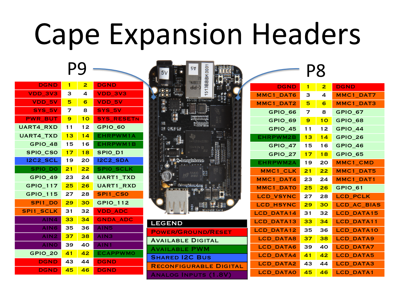
Add gpio-line-names properties to the gpio controller nodes. BeagleBone boards have P8 and P9 headers [0] which expose many the AM3358 SoC balls to stacking expansion boards called "capes", or to other external connections like jumper wires to a breadboard.
Many of the P8/P9 header pins can muxed to a gpio line. The gpio-line-names describe which P8/P9 pin that line goes to and the default mux for that P8/P9 pin. Some lines are not routed to the P8/P9 headers, but instead are dedicated to some functionality such as status LEDs. The line name will indicate this. Some line names are left empty as the corresponding AM3358 balls are not connected.
The goal is to make it easier for a user viewing the output of gpioinfo to determine which P8/P9 pin is connected to a line. The output of gpioinfo on a BeagleBone Black will now look like this:
gpiochip0 - 32 lines:
	line   0:   "ethernet"       unused   input  active-high
	line   1:   "ethernet"       unused   input  active-high
	line   2: "P9_22 spi0_sclk" unused input active-high
	line   3: "P9_21 spi0_d0" unused input active-high
	line   4: "P9_18 spi0_d1" unused input active-high
	line   5: "P9_17 spi0_cs0" unused input active-high
	line   6:    "sd card"         "cd"   input   active-low [used]
	line   7: "P9_42A ecappwm0" unused input active-high
	line   8: "P8_35 hdmi"       unused   input  active-high
	line   9: "P8_33 hdmi"       unused   input  active-high
	line  10: "P8_31 hdmi"       unused   input  active-high
	line  11: "P8_32 hdmi"       unused   input  active-high
	line  12: "P9_20 i2c2_sda" unused input active-high
	line  13: "P9_19 i2c2_scl" unused input active-high
	line  14: "P9_26 uart1_rxd" unused input active-high
	line  15: "P9_24 uart1_txd" unused input active-high
	line  16:   "ethernet"       unused   input  active-high
	line  17:   "ethernet"       unused   input  active-high
	line  18:        "usb"       unused   input  active-high
	line  19:       "hdmi"       unused   input  active-high
	line  20: "P9_41B gpio" unused input active-high
	line  21:   "ethernet"       unused   input  active-high
	line  22: "P8_19 ehrpwm2a" unused input active-high
	line  23: "P8_13 ehrpwm2b" unused input active-high
	line  24:      unnamed       unused   input  active-high
	line  25:      unnamed       unused   input  active-high
	line  26: "P8_14 gpio"       unused   input  active-high
	line  27: "P8_17 gpio"       unused   input  active-high
	line  28:   "ethernet"       unused   input  active-high
	line  29:   "ethernet"       unused   input  active-high
	line  30: "P9_11 uart4_rxd" unused input active-high
	line  31: "P9_13 uart4_txd" unused input active-high
gpiochip1 - 32 lines:
	line   0: "P8_25 emmc"       unused   input  active-high
	line   1:       "emmc"       unused   input  active-high
	line   2:  "P8_5 emmc"       unused   input  active-high
	line   3:  "P8_6 emmc"       unused   input  active-high
	line   4: "P8_23 emmc"       unused   input  active-high
	line   5: "P8_22 emmc"       unused   input  active-high
	line   6:  "P8_3 emmc"       unused   input  active-high
	line   7:  "P8_4 emmc"       unused   input  active-high
	line   8:      unnamed       unused   input  active-high
	line   9:      unnamed       unused   input  active-high
	line  10:      unnamed       unused   input  active-high
	line  11:      unnamed       unused   input  active-high
	line  12: "P8_12 gpio"       unused   input  active-high
	line  13: "P8_11 gpio"       unused   input  active-high
	line  14: "P8_16 gpio"       unused   input  active-high
	line  15: "P8_15 gpio"       unused   input  active-high
	line  16: "P9_15A gpio" unused input active-high
	line  17: "P9_23 gpio"       unused   input  active-high
	line  18: "P9_14 ehrpwm1a" unused input active-high
	line  19: "P9_16 ehrpwm1b" unused input active-high
	line  20:       "emmc"       unused   input  active-high
	line  21:   "usr0 led" "beaglebone:green:heart" output active-high [used]
	line  22:   "usr1 led" "beaglebone:green:mmc0" output active-high [used]
	line  23:   "usr2 led" "beaglebone:green:usr2" output active-high [used]
	line  24:   "usr3 led" "beaglebone:green:usr3" output active-high [used]
	line  25:       "hdmi"  "interrupt"   input  active-high [used]
	line  26:        "usb"       unused   input  active-high
	line  27: "hdmi audio"     "enable"  output  active-high [used]
	line  28: "P9_12 gpio"       unused   input  active-high
	line  29: "P8_26 gpio"       unused   input  active-high
	line  30: "P8_21 emmc"       unused   input  active-high
	line  31: "P8_20 emmc"       unused   input  active-high
gpiochip2 - 32 lines:
	line   0: "P9_15B gpio" unused input active-high
	line   1: "P8_18 gpio"       unused   input  active-high
	line   2:  "P8_7 gpio"       unused   input  active-high
	line   3:  "P8_8 gpio"       unused   input  active-high
	line   4: "P8_10 gpio"       unused   input  active-high
	line   5:  "P8_9 gpio"       unused   input  active-high
	line   6: "P8_45 hdmi"       unused   input  active-high
	line   7: "P8_46 hdmi"       unused   input  active-high
	line   8: "P8_43 hdmi"       unused   input  active-high
	line   9: "P8_44 hdmi"       unused   input  active-high
	line  10: "P8_41 hdmi"       unused   input  active-high
	line  11: "P8_42 hdmi"       unused   input  active-high
	line  12: "P8_39 hdmi"       unused   input  active-high
	line  13: "P8_40 hdmi"       unused   input  active-high
	line  14: "P8_37 hdmi"       unused   input  active-high
	line  15: "P8_38 hdmi"       unused   input  active-high
	line  16: "P8_36 hdmi"       unused   input  active-high
	line  17: "P8_34 hdmi"       unused   input  active-high
	line  18:   "ethernet"       unused   input  active-high
	line  19:   "ethernet"       unused   input  active-high
	line  20:   "ethernet"       unused   input  active-high
	line  21:   "ethernet"       unused   input  active-high
	line  22: "P8_27 hdmi"       unused   input  active-high
	line  23: "P8_29 hdmi"       unused   input  active-high
	line  24: "P8_28 hdmi"       unused   input  active-high
	line  25: "P8_30 hdmi"       unused   input  active-high
	line  26:       "emmc"       unused   input  active-high
	line  27:       "emmc"       unused   input  active-high
	line  28:       "emmc"       unused   input  active-high
	line  29:       "emmc"       unused   input  active-high
	line  30:       "emmc"       unused   input  active-high
	line  31:       "emmc"       unused   input  active-high
gpiochip3 - 32 lines:
	line   0:   "ethernet"       unused   input  active-high
	line   1:   "ethernet"       unused   input  active-high
	line   2:   "ethernet"       unused   input  active-high
	line   3:   "ethernet"       unused   input  active-high
	line   4:   "ethernet"       unused   input  active-high
	line   5:       "i2c0"       unused   input  active-high
	line   6:       "i2c0"       unused   input  active-high
	line   7:        "emu"       unused   input  active-high
	line   8:        "emu"       unused   input  active-high
	line   9:   "ethernet"       unused   input  active-high
	line  10:   "ethernet"       unused   input  active-high
	line  11:      unnamed       unused   input  active-high
	line  12:      unnamed       unused   input  active-high
	line  13:        "usb"       unused   input  active-high
	line  14: "P9_31 spi1_sclk" unused input active-high
	line  15: "P9_29 spi1_d0" unused input active-high
	line  16: "P9_30 spi1_d1" unused input active-high
	line  17: "P9_28 spi1_cs0" unused input active-high
	line  18: "P9_42B ecappwm0" unused input active-high
	line  19: "P9_27 gpio"       unused   input  active-high
	line  20: "P9_41A gpio" unused input active-high
	line  21: "P9_25 gpio"       unused   input  active-high
	line  22:      unnamed       unused   input  active-high
	line  23:      unnamed       unused   input  active-high
	line  24:      unnamed       unused   input  active-high
	line  25:      unnamed       unused   input  active-high
	line  26:      unnamed       unused   input  active-high
	line  27:      unnamed       unused   input  active-high
	line  28:      unnamed       unused   input  active-high
	line  29:      unnamed       unused   input  active-high
	line  30:      unnamed       unused   input  active-high
	line  31:      unnamed       unused   input  active-high
[0] https://beagleboard.org/Support/bone101
[1] https://beagleboard.org/capes
---
 arch/arm/boot/dts/am335x-bone-common.dtsi | 144 ++++++++++++++++++++++
 1 file changed, 144 insertions(+)
arch/arm/boot/dts/am335x-bone-common.dtsi +144 -0
@@ -397,3 +397,147 @@ clocks = <&clk_32768_ck>, <&clk_24mhz_clkctrl AM3_CLK_24MHZ_CLKDIV32K_CLKCTRL 0>; clock-names = "ext-clk", "int-clk"; }; + +&gpio0 { + gpio-line-names = + "ethernet", + "ethernet", + "P9_22 spi0_sclk", + "P9_21 spi0_d0", + "P9_18 spi0_d1", + "P9_17 spi0_cs0", + "sd card", + "P9_42A ecappwm0", + "P8_35 hdmi", + "P8_33 hdmi", + "P8_31 hdmi", + "P8_32 hdmi", + "P9_20 i2c2_sda", + "P9_19 i2c2_scl", + "P9_26 uart1_rxd", + "P9_24 uart1_txd", + "ethernet", + "ethernet", + "usb", + "hdmi", + "P9_41B gpio", + "ethernet", + "P8_19 ehrpwm2a", + "P8_13 ehrpwm2b", + "", + "", + "P8_14 gpio", + "P8_17 gpio", + "ethernet", + "ethernet", + "P9_11 uart4_rxd", + "P9_13 uart4_txd"; +}; + +&gpio1 { + gpio-line-names = + "P8_25 emmc", + "emmc", + "P8_5 emmc", + "P8_6 emmc", + "P8_23 emmc", + "P8_22 emmc", + "P8_3 emmc", + "P8_4 emmc", + "", + "", + "", + "", + "P8_12 gpio", + "P8_11 gpio", + "P8_16 gpio", + "P8_15 gpio", + "P9_15A gpio", + "P9_23 gpio", + "P9_14 ehrpwm1a", + "P9_16 ehrpwm1b", + "emmc", + "usr0 led", + "usr1 led", + "usr2 led", + "usr3 led", + "hdmi", + "usb", + "hdmi audio", + "P9_12 gpio", + "P8_26 gpio", + "P8_21 emmc", + "P8_20 emmc"; +}; + +&gpio2 { + gpio-line-names = + "P9_15B gpio", + "P8_18 gpio", + "P8_7 gpio", + "P8_8 gpio", + "P8_10 gpio", + "P8_9 gpio", + "P8_45 hdmi", + "P8_46 hdmi", + "P8_43 hdmi", + "P8_44 hdmi", + "P8_41 hdmi", + "P8_42 hdmi", + "P8_39 hdmi", + "P8_40 hdmi", + "P8_37 hdmi", + "P8_38 hdmi", + "P8_36 hdmi", + "P8_34 hdmi", + "ethernet", + "ethernet", + "ethernet", + "ethernet", + "P8_27 hdmi", + "P8_29 hdmi", + "P8_28 hdmi", + "P8_30 hdmi", + "emmc", + "emmc", + "emmc", + "emmc", + "emmc", + "emmc"; +}; + +&gpio3 { + gpio-line-names = + "ethernet", + "ethernet", + "ethernet", + "ethernet", + "ethernet", + "i2c0", + "i2c0", + "emu", + "emu", + "ethernet", + "ethernet", + "", + "", + "usb", + "P9_31 spi1_sclk", + "P9_29 spi1_d0", + "P9_30 spi1_d1", + "P9_28 spi1_cs0", + "P9_42B ecappwm0", + "P9_27 gpio", + "P9_41A gpio", + "P9_25 gpio", + "", + "", + "", + "", + "", + "", + "", + "", + "", + ""; +};
Signature · 1 line
2.20.1
Hi,
Adding Linus W to Cc, would be good to get some comments on this.
Quoted 314 lines · Drew Fustini
Add gpio-line-names properties to the gpio controller nodes. BeagleBone boards have P8 and P9 headers [0] which expose many the AM3358 SoC balls to stacking expansion boards called "capes", or to other external connections like jumper wires to a breadboard.
Many of the P8/P9 header pins can muxed to a gpio line. The gpio-line-names describe which P8/P9 pin that line goes to and the default mux for that P8/P9 pin. Some lines are not routed to the P8/P9 headers, but instead are dedicated to some functionality such as status LEDs. The line name will indicate this. Some line names are left empty as the corresponding AM3358 balls are not connected.
The goal is to make it easier for a user viewing the output of gpioinfo to determine which P8/P9 pin is connected to a line. The output of gpioinfo on a BeagleBone Black will now look like this:
gpiochip0 - 32 lines:
	line   0:   "ethernet"       unused   input  active-high
	line   1:   "ethernet"       unused   input  active-high
	line   2: "P9_22 spi0_sclk" unused input active-high
	line   3: "P9_21 spi0_d0" unused input active-high
	line   4: "P9_18 spi0_d1" unused input active-high
	line   5: "P9_17 spi0_cs0" unused input active-high
	line   6:    "sd card"         "cd"   input   active-low [used]
	line   7: "P9_42A ecappwm0" unused input active-high
	line   8: "P8_35 hdmi"       unused   input  active-high
	line   9: "P8_33 hdmi"       unused   input  active-high
	line  10: "P8_31 hdmi"       unused   input  active-high
	line  11: "P8_32 hdmi"       unused   input  active-high
	line  12: "P9_20 i2c2_sda" unused input active-high
	line  13: "P9_19 i2c2_scl" unused input active-high
	line  14: "P9_26 uart1_rxd" unused input active-high
	line  15: "P9_24 uart1_txd" unused input active-high
	line  16:   "ethernet"       unused   input  active-high
	line  17:   "ethernet"       unused   input  active-high
	line  18:        "usb"       unused   input  active-high
	line  19:       "hdmi"       unused   input  active-high
	line  20: "P9_41B gpio" unused input active-high
	line  21:   "ethernet"       unused   input  active-high
	line  22: "P8_19 ehrpwm2a" unused input active-high
	line  23: "P8_13 ehrpwm2b" unused input active-high
	line  24:      unnamed       unused   input  active-high
	line  25:      unnamed       unused   input  active-high
	line  26: "P8_14 gpio"       unused   input  active-high
	line  27: "P8_17 gpio"       unused   input  active-high
	line  28:   "ethernet"       unused   input  active-high
	line  29:   "ethernet"       unused   input  active-high
	line  30: "P9_11 uart4_rxd" unused input active-high
	line  31: "P9_13 uart4_txd" unused input active-high
gpiochip1 - 32 lines:
	line   0: "P8_25 emmc"       unused   input  active-high
	line   1:       "emmc"       unused   input  active-high
	line   2:  "P8_5 emmc"       unused   input  active-high
	line   3:  "P8_6 emmc"       unused   input  active-high
	line   4: "P8_23 emmc"       unused   input  active-high
	line   5: "P8_22 emmc"       unused   input  active-high
	line   6:  "P8_3 emmc"       unused   input  active-high
	line   7:  "P8_4 emmc"       unused   input  active-high
	line   8:      unnamed       unused   input  active-high
	line   9:      unnamed       unused   input  active-high
	line  10:      unnamed       unused   input  active-high
	line  11:      unnamed       unused   input  active-high
	line  12: "P8_12 gpio"       unused   input  active-high
	line  13: "P8_11 gpio"       unused   input  active-high
	line  14: "P8_16 gpio"       unused   input  active-high
	line  15: "P8_15 gpio"       unused   input  active-high
	line  16: "P9_15A gpio" unused input active-high
	line  17: "P9_23 gpio"       unused   input  active-high
	line  18: "P9_14 ehrpwm1a" unused input active-high
	line  19: "P9_16 ehrpwm1b" unused input active-high
	line  20:       "emmc"       unused   input  active-high
	line  21:   "usr0 led" "beaglebone:green:heart" output active-high [used]
	line  22:   "usr1 led" "beaglebone:green:mmc0" output active-high [used]
	line  23:   "usr2 led" "beaglebone:green:usr2" output active-high [used]
	line  24:   "usr3 led" "beaglebone:green:usr3" output active-high [used]
	line  25:       "hdmi"  "interrupt"   input  active-high [used]
	line  26:        "usb"       unused   input  active-high
	line  27: "hdmi audio"     "enable"  output  active-high [used]
	line  28: "P9_12 gpio"       unused   input  active-high
	line  29: "P8_26 gpio"       unused   input  active-high
	line  30: "P8_21 emmc"       unused   input  active-high
	line  31: "P8_20 emmc"       unused   input  active-high
gpiochip2 - 32 lines:
	line   0: "P9_15B gpio" unused input active-high
	line   1: "P8_18 gpio"       unused   input  active-high
	line   2:  "P8_7 gpio"       unused   input  active-high
	line   3:  "P8_8 gpio"       unused   input  active-high
	line   4: "P8_10 gpio"       unused   input  active-high
	line   5:  "P8_9 gpio"       unused   input  active-high
	line   6: "P8_45 hdmi"       unused   input  active-high
	line   7: "P8_46 hdmi"       unused   input  active-high
	line   8: "P8_43 hdmi"       unused   input  active-high
	line   9: "P8_44 hdmi"       unused   input  active-high
	line  10: "P8_41 hdmi"       unused   input  active-high
	line  11: "P8_42 hdmi"       unused   input  active-high
	line  12: "P8_39 hdmi"       unused   input  active-high
	line  13: "P8_40 hdmi"       unused   input  active-high
	line  14: "P8_37 hdmi"       unused   input  active-high
	line  15: "P8_38 hdmi"       unused   input  active-high
	line  16: "P8_36 hdmi"       unused   input  active-high
	line  17: "P8_34 hdmi"       unused   input  active-high
	line  18:   "ethernet"       unused   input  active-high
	line  19:   "ethernet"       unused   input  active-high
	line  20:   "ethernet"       unused   input  active-high
	line  21:   "ethernet"       unused   input  active-high
	line  22: "P8_27 hdmi"       unused   input  active-high
	line  23: "P8_29 hdmi"       unused   input  active-high
	line  24: "P8_28 hdmi"       unused   input  active-high
	line  25: "P8_30 hdmi"       unused   input  active-high
	line  26:       "emmc"       unused   input  active-high
	line  27:       "emmc"       unused   input  active-high
	line  28:       "emmc"       unused   input  active-high
	line  29:       "emmc"       unused   input  active-high
	line  30:       "emmc"       unused   input  active-high
	line  31:       "emmc"       unused   input  active-high
gpiochip3 - 32 lines:
	line   0:   "ethernet"       unused   input  active-high
	line   1:   "ethernet"       unused   input  active-high
	line   2:   "ethernet"       unused   input  active-high
	line   3:   "ethernet"       unused   input  active-high
	line   4:   "ethernet"       unused   input  active-high
	line   5:       "i2c0"       unused   input  active-high
	line   6:       "i2c0"       unused   input  active-high
	line   7:        "emu"       unused   input  active-high
	line   8:        "emu"       unused   input  active-high
	line   9:   "ethernet"       unused   input  active-high
	line  10:   "ethernet"       unused   input  active-high
	line  11:      unnamed       unused   input  active-high
	line  12:      unnamed       unused   input  active-high
	line  13:        "usb"       unused   input  active-high
	line  14: "P9_31 spi1_sclk" unused input active-high
	line  15: "P9_29 spi1_d0" unused input active-high
	line  16: "P9_30 spi1_d1" unused input active-high
	line  17: "P9_28 spi1_cs0" unused input active-high
	line  18: "P9_42B ecappwm0" unused input active-high
	line  19: "P9_27 gpio"       unused   input  active-high
	line  20: "P9_41A gpio" unused input active-high
	line  21: "P9_25 gpio"       unused   input  active-high
	line  22:      unnamed       unused   input  active-high
	line  23:      unnamed       unused   input  active-high
	line  24:      unnamed       unused   input  active-high
	line  25:      unnamed       unused   input  active-high
	line  26:      unnamed       unused   input  active-high
	line  27:      unnamed       unused   input  active-high
	line  28:      unnamed       unused   input  active-high
	line  29:      unnamed       unused   input  active-high
	line  30:      unnamed       unused   input  active-high
	line  31:      unnamed       unused   input  active-high
[0] https://beagleboard.org/Support/bone101
[1] https://beagleboard.org/capesReviewed-by Jason Kridner <[email protected]>Reviewed-by Robert Nelson <[email protected]>Signed-off-by Drew Fustini <[email protected]>--- arch/arm/boot/dts/am335x-bone-common.dtsi | 144 ++++++++++++++++++++++ 1 file changed, 144 insertions(+)arch/arm/boot/dts/am335x-bone-common.dtsi +144
-0@@ -397,3 +397,147 @@ clocks = <&clk_32768_ck>, <&clk_24mhz_clkctrl AM3_CLK_24MHZ_CLKDIV32K_CLKCTRL 0>; clock-names = "ext-clk", "int-clk"; }; + +&gpio0 { + gpio-line-names = + "ethernet", + "ethernet", + "P9_22 spi0_sclk", + "P9_21 spi0_d0", + "P9_18 spi0_d1", + "P9_17 spi0_cs0", + "sd card", + "P9_42A ecappwm0", + "P8_35 hdmi", + "P8_33 hdmi", + "P8_31 hdmi", + "P8_32 hdmi", + "P9_20 i2c2_sda", + "P9_19 i2c2_scl", + "P9_26 uart1_rxd", + "P9_24 uart1_txd", + "ethernet", + "ethernet", + "usb", + "hdmi", + "P9_41B gpio", + "ethernet", + "P8_19 ehrpwm2a", + "P8_13 ehrpwm2b", + "", + "", + "P8_14 gpio", + "P8_17 gpio", + "ethernet", + "ethernet", + "P9_11 uart4_rxd", + "P9_13 uart4_txd"; +}; + +&gpio1 { + gpio-line-names = + "P8_25 emmc", + "emmc", + "P8_5 emmc", + "P8_6 emmc", + "P8_23 emmc", + "P8_22 emmc", + "P8_3 emmc", + "P8_4 emmc", + "", + "", + "", + "", + "P8_12 gpio", + "P8_11 gpio", + "P8_16 gpio", + "P8_15 gpio", + "P9_15A gpio", + "P9_23 gpio", + "P9_14 ehrpwm1a", + "P9_16 ehrpwm1b", + "emmc", + "usr0 led", + "usr1 led", + "usr2 led", + "usr3 led", + "hdmi", + "usb", + "hdmi audio", + "P9_12 gpio", + "P8_26 gpio", + "P8_21 emmc", + "P8_20 emmc"; +}; + +&gpio2 { + gpio-line-names = + "P9_15B gpio", + "P8_18 gpio", + "P8_7 gpio", + "P8_8 gpio", + "P8_10 gpio", + "P8_9 gpio", + "P8_45 hdmi", + "P8_46 hdmi", + "P8_43 hdmi", + "P8_44 hdmi", + "P8_41 hdmi", + "P8_42 hdmi", + "P8_39 hdmi", + "P8_40 hdmi", + "P8_37 hdmi", + "P8_38 hdmi", + "P8_36 hdmi", + "P8_34 hdmi", + "ethernet", + "ethernet", + "ethernet", + "ethernet", + "P8_27 hdmi", + "P8_29 hdmi", + "P8_28 hdmi", + "P8_30 hdmi", + "emmc", + "emmc", + "emmc", + "emmc", + "emmc", + "emmc"; +}; + +&gpio3 { + gpio-line-names = + "ethernet", + "ethernet", + "ethernet", + "ethernet", + "ethernet", + "i2c0", + "i2c0", + "emu", + "emu", + "ethernet", + "ethernet", + "", + "", + "usb", + "P9_31 spi1_sclk", + "P9_29 spi1_d0", + "P9_30 spi1_d1", + "P9_28 spi1_cs0", + "P9_42B ecappwm0", + "P9_27 gpio", + "P9_41A gpio", + "P9_25 gpio", + "", + "", + "", + "", + "", + "", + "", + "", + "", + ""; +};Signature · 1 line
2.20.1
Quoted 12 lines · Drew Fustini
Add gpio-line-names properties to the gpio controller nodes. BeagleBone boards have P8 and P9 headers [0] which expose many the AM3358 SoC balls to stacking expansion boards called "capes", or to other external connections like jumper wires to a breadboard.
Many of the P8/P9 header pins can muxed to a gpio line. The gpio-line-names describe which P8/P9 pin that line goes to and the default mux for that P8/P9 pin. Some lines are not routed to the P8/P9 headers, but instead are dedicated to some functionality such as status LEDs. The line name will indicate this. Some line names are left empty as the corresponding AM3358 balls are not connected.
Quoted 7 lines
The goal is to make it easier for a user viewing the output of gpioinfo to determine which P8/P9 pin is connected to a line. The output of gpioinfo on a BeagleBone Black will now look like this:
gpiochip0 - 32 lines:
        line   0:   "ethernet"       unused   input  active-high
        line   1:   "ethernet"       unused   input  active-high
Why are the ethernet lines not tagged with respective signal name when right below the SPI lines are explicitly tagged with sclk, cs0 etc?
Ethernet is usually RGMII and has signal names like tx_clk, tx_d0, tx_en etc.
Also some lines seem to be tagged with the pin number like P9_22, P2_21 below, it seems a bit inconsistent to have much information on some pins and very sketchy information on some.
Quoted 2 lines
        line  18:        "usb"       unused   input  active-high
        line  19:       "hdmi"       unused   input  active-high
Similar comments for these.
Yours,
Linus Walleij
Quoted 8 lines · Linus Walleij
Quoted 3 lines
gpiochip0 - 32 lines:
        line   0:   "ethernet"       unused   input  active-high
        line   1:   "ethernet"       unused   input  active-high
Why are the ethernet lines not tagged with respective signal name when right below the SPI lines are explicitly tagged with sclk, cs0 etc?
Quoted 7 lines
Ethernet is usually RGMII and has signal names like
tx_clk,tx_d0,tx_enetc.Also some lines seem to be tagged with the pin number like
P9_22,P2_21below, it seems a bit inconsistent to have much information on some pins and very sketchy information on some.
the pin names match the beagle bone documentation and would help users figure out which pins on the expansion headers match to a gpio signal.
Signature · 1 line
balbi
Quoted 12 lines · Felipe Balbi
Quoted 11 lines · Linus Walleij
Quoted 3 lines
gpiochip0 - 32 lines:
        line   0:   "ethernet"       unused   input  active-high
        line   1:   "ethernet"       unused   input  active-high
Why are the ethernet lines not tagged with respective signal name when right below the SPI lines are explicitly tagged with sclk, cs0 etc?
Ethernet is usually RGMII and has signal names like
tx_clk,tx_d0,tx_enetc.
Quoted 7 lines
Quoted 4 lines
Also some lines seem to be tagged with the pin number like
P9_22,P2_21below, it seems a bit inconsistent to have much information on some pins and very sketchy information on some.the pin names match the beagle bone documentation and would help users figure out which pins on the expansion headers match to a gpio signal.
OK if it is how it looks in the documentation I agree that is what users need, maybe the documentation is confusing but there is not much to do about that.
Yours,
Linus Walleij
Quoted 18 lines · Linus Walleij
Quoted 17 lines · Felipe Balbi
Quoted 15 lines · Linus Walleij
Quoted 3 lines
gpiochip0 - 32 lines:
        line   0:   "ethernet"       unused   input  active-high
        line   1:   "ethernet"       unused   input  active-high
Why are the ethernet lines not tagged with respective signal name when right below the SPI lines are explicitly tagged with sclk, cs0 etc?
Ethernet is usually RGMII and has signal names like
tx_clk,tx_d0,tx_enetc.Also some lines seem to be tagged with the pin number like
P9_22,P2_21below, it seems a bit inconsistent to have much information on some pins and very sketchy information on some.
Quoted 6 lines
Quoted 2 lines
the pin names match the beagle bone documentation and would help users figure out which pins on the expansion headers match to a gpio signal.
OK if it is how it looks in the documentation I agree that is what users need, maybe the documentation is confusing but there is not much to do about that.
the board has two expansion headers, P1 and P2:
https://github.com/beagleboard/pocketbeagle/wiki/System-Reference-Manual#531_Expansion_Headers
Pins are always the pin number on the header, hence P2_21 and P1_10 and so on.
Signature · 1 line
balbi
Quoted 15 lines · Felipe Balbi
Quoted 13 lines · Linus Walleij
Quoted 12 lines · Felipe Balbi
Quoted 11 lines · Linus Walleij
Quoted 3 lines
gpiochip0 - 32 lines:
        line   0:   "ethernet"       unused   input  active-high
        line   1:   "ethernet"       unused   input  active-high
Why are the ethernet lines not tagged with respective signal name when right below the SPI lines are explicitly tagged with sclk, cs0 etc?
Ethernet is usually RGMII and has signal names like
tx_clk,tx_d0,tx_enetc.
Quoted 7 lines
Quoted 7 lines
Quoted 7 lines
Quoted 4 lines
Also some lines seem to be tagged with the pin number like
P9_22,P2_21below, it seems a bit inconsistent to have much information on some pins and very sketchy information on some.the pin names match the beagle bone documentation and would help users figure out which pins on the expansion headers match to a gpio signal.
Thank you for pointing this out. That is my goal with the line names.
Quoted 11 lines
Quoted 4 lines
OK if it is how it looks in the documentation I agree that is what users need, maybe the documentation is confusing but there is not much to do about that.
the board has two expansion headers, P1 and P2:
https://github.com/beagleboard/pocketbeagle/wiki/System-Reference-Manual#531_Expansion_Headers
Pins are always the pin number on the header, hence
P2_21andP1_10and so on.
Just to clarify, the patch was for the BeagleBone {White,Green,Black} which have P8 and P9 headers.
The PocketBeagle has lower pin count headers labeled P1 and P2. I do plan to submit a patch for am335x-pocketbeagle.dts with the respective line names, but I wanted to first integrate feedback regarding P8/P9 on the bone.
thanks,
drew
Quoted 22 lines · Linus Walleij
Quoted 12 lines · Drew Fustini
Add gpio-line-names properties to the gpio controller nodes. BeagleBone boards have P8 and P9 headers [0] which expose many the AM3358 SoC balls to stacking expansion boards called "capes", or to other external connections like jumper wires to a breadboard.
Many of the P8/P9 header pins can muxed to a gpio line. The gpio-line-names describe which P8/P9 pin that line goes to and the default mux for that P8/P9 pin. Some lines are not routed to the P8/P9 headers, but instead are dedicated to some functionality such as status LEDs. The line name will indicate this. Some line names are left empty as the corresponding AM3358 balls are not connected.
Quoted 7 lines
The goal is to make it easier for a user viewing the output of gpioinfo to determine which P8/P9 pin is connected to a line. The output of gpioinfo on a BeagleBone Black will now look like this:
gpiochip0 - 32 lines:
        line   0:   "ethernet"       unused   input  active-high
        line   1:   "ethernet"       unused   input  active-high
Quoted 6 lines
Why are the ethernet lines not tagged with respective signal name when right below the SPI lines are explicitly tagged with sclk, cs0 etc?
Ethernet is usually RGMII and has signal names like
tx_clk,tx_d0,tx_enetc.
Thank you for the feedback, Linus.
My desire is to communicate that the AM3358 balls corresponding to these GPIO lines are being used for Ethernet and not exposed to the P8 and P9 expansion headers.
I am happy to switch these labels to the actual Ethernet signals such as RGMII and MDIO signal names if you think that is better.
For example, AM3358 ZCZ ball M17 is both gpio0_0 and mdio_data [0]. On BeagleBone, the ball is routed to the Ethernet PHY and used for MDIO [1] Thus gpiochio 0 line 0 is not connected to the P8 or P9 expansion header.
Which of the following line name would be best?
1) "[MDIO_DATA]"
precise signal name, placed in brackets to denote is not possible to use as GPIO on the P8 or P9 headers
2) "[ethernet]"
instead of the precise signal name, just indicate that it is used for Ethernet and is not usable for GPIO on the P8 or P9 headers
3) ""
no label as this gpio line is not connected to the P8/P9 and is hardwired in the PCB layout for Ethernet (MDIO).
Quoted 4 lines
Also some lines seem to be tagged with the pin number like
P9_22,P2_21below, it seems a bit inconsistent to have much information on some pins and very sketchy information on some.
The goal for these line names is make it easier for a BeagleBone user to identify which GPIO lines are connected to the P8 and P9 expansion headers. Our users are most likely to refer to cape-headers.png [2] as it is part of the bone101 out-of-the-box tutorial [3].
Some GPIO lines are free to be used for GPIO in the default configuration. For example, gpiochip 1 line 12 is connected to P8_12 and it is not used by another peripheral by default. I used the label:
"P8_12 gpio"
However, gpiochip 1 line 0 is connected to P8_25 but is also used by the on-board eMMC. The eMMc is enabled by default so this line can not be used for GPIO unless the user modifies the pinmux in the device tree.
Thus, I used this label: "P8_25 emmc"
Maybe a better label would be "P8_25 [EMMC]"?
Quoted 5 lines
Quoted 3 lines
        line  18:        "usb"       unused   input  active-high
        line  19:       "hdmi"       unused   input  active-high
Similar comments for these.
These are similar to the Ethernet MDIO example above. The balls corresponding to these GPIO lines are not connected to the P8 or P9 headers and are hardwired on the PCB for other peripherals like USB and HDMI.
For example, gpiochip 0 line 18 is USB0_DRVVBUS so I simplified it to "usb" to indicate it can not be used for GPIO. Maybe "[USB]" is better?
gpiochip 0 line 19 is AM3358 ZCZ ball A15 and the BeagleBone Black schematic shows that this is connected to the CEC clock for the HDMI framer [4]. I though "hdmi" was a nice way to summarize that this is used for HDMI and can not be changed, though maybe "[HDMI]" is better or no label at all.
In conclusion, the motivation of these line names is to be a quick reference for a user to find GPIO lines on the P8 and P9 headers.
Thanks,
Drew
[0] http://www.ti.com/lit/ds/symlink/am3358.pdf
[1] https://github.com/beagleboard/beaglebone-black/wiki/System-Reference-Manual#ethernet-processor-interface
[2] http://beagleboard.org/static/images/cape-headers.png
[3] https://beagleboard.org/Support/bone101
[4] https://github.com/beagleboard/beaglebone-black/blob/master/BBB_SCH.pdf
Quoted 107 lines · Drew Fustini
Quoted 22 lines · Linus Walleij
Quoted 12 lines · Drew Fustini
Add gpio-line-names properties to the gpio controller nodes. BeagleBone boards have P8 and P9 headers [0] which expose many the AM3358 SoC balls to stacking expansion boards called "capes", or to other external connections like jumper wires to a breadboard.
Many of the P8/P9 header pins can muxed to a gpio line. The gpio-line-names describe which P8/P9 pin that line goes to and the default mux for that P8/P9 pin. Some lines are not routed to the P8/P9 headers, but instead are dedicated to some functionality such as status LEDs. The line name will indicate this. Some line names are left empty as the corresponding AM3358 balls are not connected.
Quoted 7 lines
The goal is to make it easier for a user viewing the output of gpioinfo to determine which P8/P9 pin is connected to a line. The output of gpioinfo on a BeagleBone Black will now look like this:
gpiochip0 - 32 lines:
        line   0:   "ethernet"       unused   input  active-high
        line   1:   "ethernet"       unused   input  active-high
Quoted 6 lines
Why are the ethernet lines not tagged with respective signal name when right below the SPI lines are explicitly tagged with sclk, cs0 etc?
Ethernet is usually RGMII and has signal names like
tx_clk,tx_d0,tx_enetc.Thank you for the feedback, Linus.
My desire is to communicate that the AM3358 balls corresponding to these GPIO lines are being used for Ethernet and not exposed to the P8 and P9 expansion headers.
I am happy to switch these labels to the actual Ethernet signals such as RGMII and MDIO signal names if you think that is better.
For example, AM3358 ZCZ ball M17 is both
gpio0_0andmdio_data[0]. On BeagleBone, the ball is routed to the Ethernet PHY and used for MDIO [1] Thus gpiochio 0 line 0 is not connected to the P8 or P9 expansion header.Which of the following line name would be best?
1) "[
MDIO_DATA]"precise signal name, placed in brackets to denote is not possible to use as GPIO on the P8 or P9 headers
2) "[ethernet]"
instead of the precise signal name, just indicate that it is used for Ethernet and is not usable for GPIO on the P8 or P9 headers
3) ""
no label as this gpio line is not connected to the P8/P9 and is hardwired in the PCB layout for Ethernet (MDIO).
Quoted 4 lines
Also some lines seem to be tagged with the pin number like
P9_22,P2_21below, it seems a bit inconsistent to have much information on some pins and very sketchy information on some.The goal for these line names is make it easier for a BeagleBone user to identify which GPIO lines are connected to the P8 and P9 expansion headers. Our users are most likely to refer to cape-headers.png [2] as it is part of the bone101 out-of-the-box tutorial [3].
Some GPIO lines are free to be used for GPIO in the default configuration. For example, gpiochip 1 line 12 is connected to
P8_12and it is not used by another peripheral by default. I used the label:
"P8_12gpio"However, gpiochip 1 line 0 is connected to
P8_25but is also used by the on-board eMMC. The eMMc is enabled by default so this line can not be used for GPIO unless the user modifies the pinmux in the device tree.Thus, I used this label: "
P8_25emmc"Maybe a better label would be "
P8_25[EMMC]"?Quoted 5 lines
Quoted 3 lines
        line  18:        "usb"       unused   input  active-high
        line  19:       "hdmi"       unused   input  active-high
Similar comments for these.
These are similar to the Ethernet MDIO example above. The balls corresponding to these GPIO lines are not connected to the P8 or P9 headers and are hardwired on the PCB for other peripherals like USB and HDMI.
For example, gpiochip 0 line 18 is
USB0_DRVVBUSso I simplified it to "usb" to indicate it can not be used for GPIO. Maybe "[USB]" is better?gpiochip 0 line 19 is AM3358 ZCZ ball A15 and the BeagleBone Black schematic shows that this is connected to the CEC clock for the HDMI framer [4]. I though "hdmi" was a nice way to summarize that this is used for HDMI and can not be changed, though maybe "[HDMI]" is better or no label at all.
In conclusion, the motivation of these line names is to be a quick reference for a user to find GPIO lines on the P8 and P9 headers.
Quoted 9 lines
Thanks,
Drew[0] http://www.ti.com/lit/ds/symlink/am3358.pdf
[1] https://github.com/beagleboard/beaglebone-black/wiki/System-Reference-Manual#ethernet-processor-interface
[2] http://beagleboard.org/static/images/cape-headers.png
[3] https://beagleboard.org/Support/bone101
[4] https://github.com/beagleboard/beaglebone-black/blob/master/BBB_SCH.pdf
I've posted a v2 which I hope improves the intent of the line names. [0]
I'm happy to integrate any feedback and create a v3 - especially if it is prefered for me to list the specific peripherial signals instead of an abstract term like "[ethernet]" or "[emmc]". This is for lines that can not be used because they are not routed to the expansion headers.
thanks,
drew
[0] https://lore.kernel.org/linux-omap/20200520214757.GA362547@x1/T/#u
Linus Walleij
Acked-byQuoted 8 lines · Drew Fustini
I've posted a v2 which I hope improves the intent of the line names. [0]
I'm happy to integrate any feedback and create a v3 - especially if it is prefered for me to list the specific peripherial signals instead of an abstract term like "[ethernet]" or "[emmc]". This is for lines that can not be used because they are not routed to the expansion headers.
[0] https://lore.kernel.org/linux-omap/20200520214757.GA362547@x1/T/#u
This looks good to me. FWIW
Yours,
Linus Walleij
Quoted 9 lines · Linus Walleij
Quoted 7 lines · Drew Fustini
I've posted a v2 which I hope improves the intent of the line names. [0]
I'm happy to integrate any feedback and create a v3 - especially if it is prefered for me to list the specific peripherial signals instead of an abstract term like "[ethernet]" or "[emmc]". This is for lines that can not be used because they are not routed to the expansion headers.
Quoted 7 lines
Quoted 1 line
[0] https://lore.kernel.org/linux-omap/20200520214757.GA362547@x1/T/#u
This looks good to me. FWIW
Acked-by Linus Walleij <[email protected]>Yours,
Linus Walleij
Linus -
I have posted a newer patch that targets am335x-beagleblack.dts [0] instead of am335x-bone-common.dtsi as Grygorii Strashko pointed out that these line names are not applicable to all BeagleBone models.
The gpio line naming scheme is the same, is it ok to add your Ack?
thanks,
drew
[0] https://lore.kernel.org/linux-omap/20200521200926.GC429020@x1/
Quoted 18 lines · Drew Fustini
Quoted 9 lines · Linus Walleij
Quoted 7 lines · Drew Fustini
I've posted a v2 which I hope improves the intent of the line names. [0]
I'm happy to integrate any feedback and create a v3 - especially if it is prefered for me to list the specific peripherial signals instead of an abstract term like "[ethernet]" or "[emmc]". This is for lines that can not be used because they are not routed to the expansion headers.
Quoted 7 lines
Quoted 1 line
[0] https://lore.kernel.org/linux-omap/20200520214757.GA362547@x1/T/#u
This looks good to me. FWIW
Acked-by Linus Walleij <[email protected]>Yours,
Linus Walleij
Quoted 7 lines
Linus -
I have posted a newer patch that targets
am335x-beagleblack.dts[0] instead ofam335x-bone-common.dtsias Grygorii Strashko pointed out that these line names are not applicable to all BeagleBone models.The gpio line naming scheme is the same, is it ok to add your Ack?
Yes FWIW
Acked-by.
Linus Walleij